SX1211-11SKA868 Semtech, SX1211-11SKA868 Datasheet
SX1211-11SKA868
Specifications of SX1211-11SKA868
SX1211-11SK868
SX1211-SKA868
SX1211-SKA868
SX1211SK868
SX1211SK868
Available stocks


Related parts for SX1211-11SKA868


SX1211-11SKA868 Summary of contents
Page 1
... SX1211 Low Power ISM Transceiver Rev1.1 SX1211SK868/915 User Guide TN1211.01 Evaluation Kit User Guide www.semtech.com ...
Page 2
... Highlights ............................................................................................................................... 5 2.3 What the SX1211SK is .......................................................................................................... 5 2.4 How the Starter Kit Helps You ............................................................................................... 5 2.5 SX1211SK Kit Components................................................................................................... 5 2.6 Installing SX1211 SK - Hardware .......................................................................................... 5 2.7 SX1211SK – “Graphical User Interface” Software ................................................................ 6 3 SX1211SK - Tutorial ........................................................................................................................ 7 3.1 Introduction ............................................................................................................................ 7 3.2 Highlights ............................................................................................................................... 7 3.3 Reviewing Hardware.............................................................................................................. 7 3.4 System Description................................................................................................................ 7 3 ...
Page 3
... Select Mode and Operating Mode .................................................................................. 18 5.4.5 SX1211 Status display .................................................................................................... 18 5.4.6 SX1211SK Control Window ............................................................................................ 19 5.4.7 Application Selection Window ......................................................................................... 20 5.5 SX1211SK MENU Bar and Sub-Menu option ..................................................................... 21 5.5.1 Com Port ......................................................................................................................... 21 5.5.2 Band ................................................................................................................................ 21 5.5.3 Pre-defined ...................................................................................................................... 22 5.5.4 Ping - Pong...................................................................................................................... 22 5.5.5 Sync Word ....................................................................................................................... 23 6 Advance features ........................................................................................................................... 23 6 ...
Page 4
... Chapter 2: Overview and Installation - What SX1211SK is and how it can help you, how to install the hardware and the software. Chapter 3: SX1211SK - Tutorial - A tutorial on using the Starter Kit with a SX1211 RF Module. Chapter 4: Functional Overview - A description of each application mode embedded in the kit. Chapter 5: Test and Evolution - A description of the basic features to evaluate the SX1211 Chapter 6: Advanced Features - A description of specific SX1211’ ...
Page 5
... INTRODUCTION This chapter gives you an overview of the SX1211SK and then explains how to install the system hardware and software. 2.2 HIGHLIGHTS The items discussed in this chapter include: What the SX1211SK is How SX1211SK helps you SX1211SK - Kit Components Installing SX1211SK Hardware Installing SX1211SK “Graphical User Interface” software 2 ...
Page 6
... The Graphic User Interface software screen follows standard WINDOWS™ Conventions. The PC GUI provides an interactive user interface for selecting and modifying SX1211 parameters. A brief description of the screen layout and usage of the GUI interface can be found in the particular “SX1211 – Test and Evaluation” section. ...
Page 7
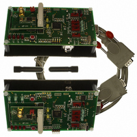
... One objective of this Starter Kit is to demonstrate a two way communication between two radio modules, but also to evaluate the SEMTECH transceiver SX1211. In order to have a high flexibility, the Starter Kit board has been developed in order to support all the SX1211 RF modules and so few buttons have been added to the board (see Figure 3.1). ...
Page 8
... Brief narrative of LEDs and push buttons Power : Switch on or switch off the power supply Frequency band : Switch to select the frequency band according to the SX1211 frequency band RF Output Power : LEDs which indicate the transmitted output power: 10 -2, -5dBm RF power Selection : Push button used to select the desired output power value Frequencies : LEDs which indicate the frequency used ...
Page 9
... Yes Change Frequency Figure 3.2: Ping. Pong Test Flowchart overview Note: The user can change the frequency of the receiver (Slave) at anytime by pushing on the "Frequency Selection” button. Rev1.1 SX1211SK868/915 User Guide Master Initialization Receiver mode mode Message Correct? Led Rx On Message ...
Page 10
... Select a Master and a Slave Ping Pong Test End Settings Auto jump mode Figure 3.3: Ping-Pong Settings flowchart Rev1.1 SX1211SK868/915 User Guide Refer to paragraph 3.6.1 Refer to paragraph 3.6.2 Refer to paragraph 3.6.3 Refer to paragraph 3.6.4 Refer to paragraph 3.6.5 and 3.6.5 TX LED is blinking RX LED in On Refer to paragraph 3 ...
Page 11
... Autojump Mode: Push up the button C0 on the Master board (the green LED switches ON) to select the Automatic Mode still down. The board is now in automatic mode; the user can not change the frequency manually but can still modify the output power. Rev1.1 SX1211SK868/915 User Guide Warning Warning ...
Page 12
... FUNCTIONAL OVERVIEW 4.1 INTRODUCTION After using the Ping Pong Demo, you are ready to start using the kit. 4.2 HIGHLIGHTS SX1211SK - Functional flow chart Default Ping Pong Test User Ping Pong Test Stand Alone Evaluation Mode PC – GUI command Rev1.1 SX1211SK868/915 User Guide ...
Page 13
... RS232 port for a valid user request from the PC GUI software. Acceptance and execution of a request is indicated by the “blinking” of both yellow LEDs Rx and Tx together. If the PC is not attached, the SX1211SK will assume “SX1211 Evaluation” mode if the user has disabled the Ping-Pong Test, otherwise the “embedded software” will check if the user has defined a “ ...
Page 14
... To read the Default Ping Pong configuration saved in the Microcontoller memory, the user needs to click on “SX1211 Eval” to have access to the control buttons. Click on “Get Config”, do not click on “Load Config”. The Graphic Interface will display the Default Ping Pong configuration which has been saved into the microcontroller ...
Page 15
... Stand Alone Evaluation enabling To have access to this mode the user needs to click on “SX1211 Eval” button placed on the PC GUI interface. When all the bits have been set correctly, the configuration will be set to the microcontroller by clicking on “Send Config” and saved in the EEPROM by clicking on “Save Config”. The user can then disconnect the board from the RS232 cable ...
Page 16
... SX1211SK PC-GUI SCREEN AREAS 5.4.1 Menu Bar The MENU Bar allows the user to select the Com_Port that the board is attached to. Reset registers, Band, Pre-Defined SX1211 Settings, Ping Pong, Sync Word, Data Handler and Help are included in the menu. Rev1.1 SX1211SK868/915 User Guide A ...
Page 17
... Binary Registers The user can select a register by clicking on the register’s name tab and can select individual bit settings for a particular SX1211 register. The new settings of the register occur only when Send Config button is clicked. RSSI Measurement The RSSI measurement button is available only if the RSSI is enabled and then the PC-GUI displays the result of the measurement ...
Page 18
... Crystal). The RF Frequency can be adjusted thanks to the RPS slide-bars or directly by entering the value in the text window. In addition, the SX1211 offers the possibility to set two RF frequencies defined by Set 0 and Set 1 RPS Calculator A text window (Target RF frequency) allows entering the Local frequency through the keyboard ...
Page 19
... This operation sends all the registers to the microcontroller in order to program the SX1211 with the new configuration. Get config By clicking on this button, the user will be able to read the values of the SX1211 registers. This operation is very useful to find out what the previous programmed configuration was in the transceiver. ...
Page 20
... This mode allows the user to evaluate the SX1211 performances but also to program other parameters for the User Ping-Pong test. For more information about SX1211 registers, please refer to the SEMTECH SX1211 Datasheet. When the board is connected to the PC, the user can evaluate the performance of the SX1211 transceiver by connecting a spectrum analyzer generator. Rev1.1 SX1211SK868/915 User Guide = 908 ...
Page 21
... Band The SX1211 Band set sub-menus will allow the user to select the operating radio spectrum or the band that the SX1211 RF module being tested is designed for. Note: The 915MHz band is subdivided in two bands, 902-915MHz and 915-928MHz but can be address with the same hardware (RF module) ...
Page 22
... Ping - Pong By default the Ping Pong mode is activated when connected to the board. If the user wants to alter the Ping Pong, each board needs to be connected temporarily to the PC and the SX1211 Evaluation Application needs to be selected. In addition the user can also change the three frequencies used in the Ping Pong demo. Upon completion of desired settings, the user needs to select “ ...
Page 23
... BUFFERED HANDLER TX The GUI interface for the SX1211SK offers the advantage to program a pattern generator (Transmitter FIFO Handler). This mode is available only if the SX1211 RF module has been set in transmitter mode with the Buffered mode enabled (MCParam, Address 1, bit 5). Rev1.1 SX1211SK868/915 User Guide www ...
Page 24
... The SX1211 FIFO used in receiver mode can be displayed by the GUI interface. The Receiver FIFO is accessible only if the SX1211SK is in receiver mode and if the Buffered mode has been selected. The interrupt configuration (IRQ0 and IRQ1) will affect the way to fill the FIFO. For more information about the SX1211 interrupts, please refer to the SEMTECH Datasheet SX1211 ...
Page 25
... A: FIFO Content, display the bytes received by the SX1211 RF module. The latest byte received is store in byte FIFO (First In First Out). B: IRQs Configuration Examples shows four ways to fill the FIFO. 1. FIFO Full, the FIFO is displayed only when 16 bytes are received 2. Pattern + FIFO Full, the FIFO is filled only after the pattern detection and after the reception of 16 bytes. The pattern will not be stored in the FIFO’ ...
Page 26
... The Semtech transceiver SX1211 embeds a packet handling mode, useful to reduce the software complexity and microcontroller tasks. For more information, please refer to SX1211 Datasheet. The SX1211 Starter Kit from Y-Lynx, allows the user to play with the packet handler in transmitter as well as in receiver. ...
Page 27
... E: CRC: The CRC is used for checking the integrity of the message. The two byte CRC checksum is calculated on the payload part of the packet and appended to the end of the message F: DC Free Encoding: Two methods of en coding are available with the SX1211, the Manchester encoding and the Withering encoding. For more information, please refer to the Semtech SX1211 Datasheet ...
Page 28
... E: CRC: The CRC is used for checking the integrity of the message. The status is display thanks to a LED on the screen called CRC_status Free Encoding: Two methods of en coding are available with the SX1211, the Manchester encoding and the Withering encoding. For more information, please refer to the Semtech SX1211 Datasheet ...
Page 29
... PING – PONG TEST AND COMMUNICATION QUALITY Another Ping Pong test is embedded with the SX1211 Starter Kit and allows evaluating the communication quality in term of Packet Error Rate during the data transfer. These second ping pong test is established between a starter kit board connected and set as Master and a slave in stand-alone or connected and set as Slave. To activate the communication quality window, click on Default ping pong mode to launch “ ...
Page 30
... Check the power supply Verify that the SX1211SK is powered (the LED power indicator is ON) Verify that the SX1211 RF module is well powered. If the SX1211SK is battery operated, a jumper must be placed on module (default configuration) Verify that the voltage of the battery or of the external source is between 2.4V and 3.6V. ...