RF-TO-USB-RD Silicon Laboratories Inc, RF-TO-USB-RD Datasheet
RF-TO-USB-RD
Specifications of RF-TO-USB-RD


Related parts for RF-TO-USB-RD


RF-TO-USB-RD Summary of contents
Page 1
... When the Network UART Demo Demo GUI GUI USB Dongle HID Bootloader App Firmware Image EZRadioPRO Figure 1. System Diagram Copyright © 2009 by Silicon Laboratories ’ UIDE Node Network Node App UART Node App EZRadioPRO RF-to-USB-RD ...
Page 2
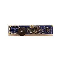
... RF-to-USB-RD 3. Hardware Overview and Setup Figure 2 and Figure 3 identify the major components of the Sensor Node and the USB Dongle. Both devices come preloaded with the firmware for the demo applications. When using the demo applications, ensure that the printed antenna on the wireless board is not covered by the user’s fingers. ...
Page 3
... Click Identify in the application. This will trigger the yellow LED on the USB Dongle to blink, indicating that there is basic communication between the application and USB Dongle 4. Click Connect to start communication with the USB Dongle. The application might prompt to update the USB Dongle firmware. Click Yes to continue. RF-to-USB-RD Rev. 0.1 3 ...
Page 4
... RF-to-USB-RD Figure USB Network Demo Application Initial Screen 5. Insert the AAA battery. If the battery has already been installed, please remove the AAA battery, press the button for at least one second to discharge the capacitor, release the button, then re-insert the battery. This will reset the MCU on the Sensor Node ...
Page 5
... UART demo. If the Sensor Node LEDs blink for more than ten seconds running the UART demo. Remove the battery, and reset the MCU. If the USB Dongle red LED illuminates continuously, this indicates a hardware error has occurred. Unplug the USB Dongle from the PC and try again. RF-to-USB-RD Rev. 0.1 5 ...
Page 6
... RF-to-USB- USB UART Demo The RF to USB UART Demo shows how a Sensor Node can be used as a wireless link to transmit data between two systems. The Sensor Node has four test points for the UART interface, as shown in Figure 6. In order to perform this demo, an external UART device must be connected to the UART interface. The UART interface operates at 19,200 baud, 8 data bits, no parity, one stop bit (8-N-1), and no handshaking ...
Page 7
... Sensor Node which will transmit it to the external device. If the device is configured for loopback mode, the transmitted data is sent back to the PC. 6. Send data from the external UART device to have it appear in the Receive text box. The received text is displayed in both hex and ASCII formats. RF-to-USB-RD Rev. 0.1 7 ...
Page 8
... RF-to-USB-RD Figure USB UART Demo Application During Communication When the Sensor Node receives any UART data on the RX pin, it will wake from the low power mode and transmit data immediately. The Sensor Node also polls the USB Dongle once per second. If there is any data waiting, the Sensor Node will retrieve pending data ...
Page 9
... The output power is +13 dB for both the USB Dongle and Sensor Node. The PCB antennas on both Sensor Node and USB Dongle are designed for lowest possible cost, not maximum range. For firmware source code or additional information, please contact MCU support. http://www.silabs.com/support/ RF-to-USB-RD Rev. 0.1 ® PRO. The RF link ...
Page 10
... RF-to-USB-RD 10 Rev. 0.1 ...
Page 11
... RF-to-USB-RD Rev. 0.1 11 ...
Page 12
... RF-to-USB-RD 12 Rev. 0.1 ...
Page 13
... N : OTES RF-to-USB-RD Rev. 0.1 13 ...
Page 14
... RF-to-USB- ONTACT NFORMATION Silicon Laboratories Inc. 400 West Cesar Chavez Austin, TX 78701 Tel: 1+(512) 416-8500 Fax: 1+(512) 416-9669 Toll Free: 1+(877) 444-3032 Please visit the Silicon Labs Technical Support web page: https://www.silabs.com/support/pages/contacttechnicalsupport.aspx and register to submit a technical support request. The information in this document is believed to be accurate in all respects at the time of publication but is subject to change without notice. ...