RN-111B-EVAL Roving Networks Inc, RN-111B-EVAL Datasheet - Page 6
RN-111B-EVAL
Manufacturer Part Number
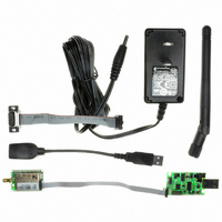
RN-111B-EVAL
Description
EVALUATION KIT FOR WIFLY MODULE
Manufacturer
Roving Networks Inc
Type
WiFly 802.11br
Specifications of RN-111B-EVAL
Frequency
2.4GHz
Wireless Frequency
50 Hz to 60 Hz
Interface Type
USB, Serial, SMA
Operating Voltage
5 VDC
Lead Free Status / RoHS Status
Lead free / RoHS Compliant
Lead Free Status / RoHS Status
Lead free / RoHS Compliant, Lead free / RoHS Compliant
Other names
740-1027


1. Reset circuit. Reset is active LOW, is optional and does not need to be connected. There is a built in voltage
2. Powering the WiFly Module. There are 3 options to power the RN-111b.
3. Factory reset PIO9 (pin 8). It is a good idea to connect this pin to a switch, or jumper, or resistor, so it can be
4. GPIO connections: Placing 3.3Vdc into the PIO’s while they are set as outputs will permanently damage the
5. Sensor connections. The Sensor inputs SENS1-8 are extremely sensitive to over voltage. Under no conditions
6. Connection status. PIO5 is available to drive an LED, and blinks at various speeds to indicate status. PIO2 is
7. Using SPI bus for flash upgrade. While not required, this bus is very useful for configuring advanced
8. Minimizing Radio interference. When integrating the WiFly module with on board chip antenna be sure the
9. Connecting to the GPIO. Placing 3.3Vdc into the PIO’s while they are set as outputs will permanently damage
Design Concerns
monitor that will pull Reset LOW (open drain FET) if the input voltage drops below 2.7VDC. If external reset is
desired, use an OPEN DRAIN driver and do not drive the Reset pin to any voltage > 1.0 Vdc.
•
•
•
If VIN is powered, VREG will supply 3.3VDC output and can be used for other circuits, with a current limitation of
50 ma.
Warning: Placing 5VDC or any voltage above 3.3Vdc into the VDD pins of the module will permanently damage
the radio module. Be sure to use the VIN = pin 13 power pin for any power supplied that is > 3.3VDC.
accessed. This pin can be used to reset the module to FACTORY DEFAULTS and is often critical in situations
where the module has been mis-configured.
radio modules. The failure mode is a short across GND and VCC. Use a 10K resistor in series or a 10K pull
up resistor for input and output PIO’s respectively.
should these pins be pulled high above 1.2VDC. Placing any voltage above this will permanently damage the
radio module.
an output which directly reflects the connection state, it goes HIGH when connected, and LOW otherwise.
parameters of the WiFly module. A 6pin header which can be implemented to gain access to this bus. A
minimum-mode version could just use the SPI signals (4pins) and pickup ground and VCC from elsewhere on the
design.
area around the chip antenna end the module protrudes at least 5mm from the PCB and any metal enclosure. If
this is not possible use the RN-111B-E (SMA jack) or RN-111B-R (Reverse polarity jack).
the radio. The failure mode is short across GND and VCC. Use a 10KO resistor is series or a 10KO pull up
resistor for input and output PIO’s respectively.
• Make sure to connect a common ground when using the external TX, RX inputs on the 0 – 3.3Vdc
• For a 3 wire DB-9 interface (tx, rx, gnd only) connect/short CTS to RTS, Factory default is hardware flow control
www.rovingnetworks.com
Supply 3.6 to 16VDC power to VIN (pin 13). Tie VREG (pin 14) to VBATT(pin 15).
Apply 3.3VDC regulated power to VDD (pin 17).
Apply battery = 2.0 to 3.0VDc to VBATT (pin 15).
enabled CTS and RTS connected.
809 University Avenue
•
Los Gatos, CA 95032
•
Tel (408) 395-6539
• info@RovingNetworks.com
DS-RN111B_V1 4/20/2009
RN-111B
Related parts for RN-111B-EVAL
Image
Part Number
Description
Manufacturer
Datasheet
Request
R

Part Number:
Description:
MODULE WIFLY 802.11B SMA
Manufacturer:
Roving Networks Inc
Datasheet:

Part Number:
Description:
MODULE WIFLY 802.11B RP-SMA
Manufacturer:
Roving Networks Inc
Datasheet:

Part Number:
Description:
MODULE WIFLY 802.11B CHIP ANT
Manufacturer:
Roving Networks Inc
Datasheet:

Part Number:
Description:
MODULE WIFLY 802.11B 1/4 WV-WIRE
Manufacturer:
Roving Networks Inc
Datasheet:

Part Number:
Description:
ADAPTER BLUETOOTH FRFLY SRL MALE
Manufacturer:
Roving Networks Inc
Datasheet:

Part Number:
Description:
ADAPTER BLUETOOTH FIREFLY RS422
Manufacturer:
Roving Networks Inc
Datasheet:

Part Number:
Description:
ADAPTER BLUETOOTH FRFLY SRL MALE
Manufacturer:
Roving Networks Inc
Datasheet:

Part Number:
Description:
ADAPTER BLUETOOTH FRFLY SRL MALE
Manufacturer:
Roving Networks Inc
Datasheet:

Part Number:
Description:
RES 11 OHM 1/4W 1% AXIAL
Manufacturer:
Stackpole Electronics Inc
Datasheet:
Part Number:
Description:
RES 11 OHM 1/4W 5% AXIAL
Manufacturer:
Stackpole Electronics Inc
Datasheet:
Part Number:
Description:
RES 11 OHM 1/2W 1% AXIAL
Manufacturer:
Stackpole Electronics Inc
Datasheet:
Part Number:
Description:
RES 11 OHM 1/4W 1% AXIAL
Manufacturer:
Stackpole Electronics Inc
Datasheet:
Part Number:
Description:
RES 11 OHM 1/2W 1% AXIAL
Manufacturer:
Stackpole Electronics Inc
Datasheet:

Part Number:
Description:
MODULE SOCKET BLUETOOTH CLASS1
Manufacturer:
Roving Networks Inc
Datasheet:

Part Number:
Description:
MODULE BLUETOOTH V2.1+EDR
Manufacturer:
Roving Networks Inc
Datasheet: