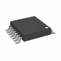
AD8343ARUZ Analog Devices Inc, AD8343ARUZ Datasheet - Page 3

AD8343ARUZ
Manufacturer Part Number
AD8343ARUZ
Description
IC MIXER ACTIVE HI-IP3 14-TSSOP
Manufacturer
Analog Devices Inc
Series
AD8343r
Datasheet
1.AD8343ARUZ.pdf
(32 pages)
Specifications of AD8343ARUZ
Frequency
0Hz ~ 2.5GHz
Rf Type
Cellular, WLAN
Number Of Mixers
1
Gain
7dB
Noise Figure
14dB
Secondary Attributes
Up/Down Converter
Current - Supply
60mA
Voltage - Supply
4.5 V ~ 5.5 V
Package / Case
14-TSSOP (0.173", 4.40mm Width)
Supply Voltage Range
4.5V To 5.5V
Rf Ic Case Style
TSSOP
No. Of Pins
14
Operating Temperature Range
-40°C To +85°C
Msl
MSL 1 - Unlimited
Ic Function
IF Subsystem
Termination Type
SMD
Supply Voltage Min
4.5V
Rohs Compliant
Yes
Operating Temperature (min)
-40C
Operating Temperature (max)
85C
Operating Temperature Classification
Industrial
Filter Terminals
SMD
Digital Ic Case Style
TSSOP
Lead Free Status / RoHS Status
Lead free / RoHS Compliant
Lead Free Status / RoHS Status
Lead free / RoHS Compliant, Lead free / RoHS Compliant
Available stocks
Company
Part Number
Manufacturer
Quantity
Price
Company:
Part Number:
AD8343ARUZ
Manufacturer:
ANALOGDE
Quantity:
2 035
Part Number:
AD8343ARUZ
Manufacturer:
ADI/亚德诺
Quantity:
20 000
SPECIFICATIONS
BASIC OPERATING INSTRUCTIONS
V
Table 1.
Parameter
INPUT INTERFACE (INPP, INPM)
OUTPUT INTERFACE (OUTP, OUTM)
LO INTERFACE (LOIP, LOIM)
POWER-DOWN INTERFACE (PWDN)
POWER SUPPLY
1
2
3
The balance in the bias current in the two legs of the mixer input is important to applications where a low feedthrough of the local oscillator (LO) is critical.
This voltage is proportional to absolute temperature (PTAT). See the DC Coupling the LO section for more information regarding this interface.
Response time until device meets all specified conditions.
S
= 5.0 V, T
Differential Open Emitter
Differential Open Collector
Differential Common Base Stage
PWDN Threshold
PWDN Response Time
PWDN Input Bias Current
Supply Voltage Range
Total Quiescent Current
Powered-Down Current
DC Bias Voltage
Operating Current Each Input (I
Value of Bias Setting Resistor
Port Differential Impedance
DC Bias Voltage
Voltage Swing
Operating Current Each Output
Port Differential Impedance
DC Bias Voltage
LO Input Power
Port Differential Reflection Coefficient
A
= 25°C, unless otherwise noted.
2
3
1
O
)
Conditions/Comments
Internally generated
Current set by R3, R4; see Figure 72
1% bias resistors; R3, R4; see Figure 72
f = 50 MHz; R3 and R4 = 68.1 Ω; see Figure 57
Externally applied
Collector bias (V
Same as input current
f = 50 MHz; see Figure 60
Internally generated; (port is typically ac-coupled)
50 Ω impedance; see Figure 65
See Figure 64
Assured on
Assured off
Time from device on to off; see Figure 52
Time from device off to on; see Figure 53
PWDN = 0 V (device on)
PWDN = 5 V (device off )
R3 and R4 = 68.1 Ω; see Figure 72
Over temperature
V
V
Over temperature; V
S
S
= 5.5 V
= 4.5 V
Rev. B | Page 3 of 32
S
) = VPOS
S
= 5.5 V
Min
1.1
5
4.5
1.65
300
−12
V
4.5
S
− 0.5
17.6
68.1
5.6 + j 1.4
V
900 − j 77
360
−10
−10
2.2
500
0
5.0
50
20
6
50
Typ
1.2
5
I
−160
O
S
± 1
Max
1.3
20
5.5
V
450
−3
V
−250
5.5
60
75
95
15
150
S
S
+ 2
− 1.5
AD8343
Unit
mA
Ω
Ω
V
mA
Ω
mV
dBm
dB
V
V
μs
ns
μA
V
mA
mA
μA
μA
μA
V
V
μA


