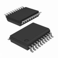
SA58640DK,112 NXP Semiconductors, SA58640DK,112 Datasheet - Page 3

SA58640DK,112
Manufacturer Part Number
SA58640DK,112
Description
IC MIXER FM IF SYSTEM 20SSOP
Manufacturer
NXP Semiconductors
Series
SA58640r
Specifications of SA58640DK,112
Package / Case
20-SSOP
Current - Supply
6mA
Voltage - Supply
4.5 V ~ 6 V
Frequency
150MHz
Rf Type
Cordless Phones
Gain
17dB
Noise Figure
7dB
Secondary Attributes
Up Converter
Number Of Mixers
2
Maximum Input Frequency
100 MHz
Mounting Style
SMD/SMT
Maximum Power Gain
17 dB
Operating Supply Voltage
5 V
Maximum Operating Temperature
+ 85 C
Minimum Operating Temperature
- 40 C
Operating Temperature (min)
-40C
Operating Temperature (max)
85C
Operating Temperature Classification
Industrial
Lead Free Status / RoHS Status
Lead free / RoHS Compliant
Lead Free Status / RoHS Status
Lead free / RoHS Compliant, Lead free / RoHS Compliant
Other names
935277002112::SA58640DK::SA58640DK
Philips Semiconductors
8. Functional description
1.
9397 750 14161
Product data sheet
dB(V) = 20log V
7.2 Pin description
o
/V
i.
Table 2:
The SA58640 is an IF signal processing system suitable for second IF systems with input
frequency as high as 100 MHz. The bandwidth of the IF amplifier and limiter is at least
2 MHz with 90 dB of gain. The gain/bandwidth distribution is optimized for 455 kHz,
1.5 k source applications. The overall system is well-suited to battery operation as well
as and high quality products of all types.
The input stage is a Gilbert cell mixer with oscillator. Typical mixer characteristics include
a noise figure of 7.0 dB, conversion gain of 17 dB, and input third-order intercept of
Hartley or Colpitts circuits can be used up to 100 MHz for crystal configurations.
The output impedance of the mixer is a 1.5 k resistor permitting direct connection to a
455 kHz ceramic filter. The input resistance of the limiting IF amplifiers is also 1.5 k . With
most 455 kHz ceramic filters and many crystal filters, no impedance matching network is
necessary. The IF amplifier has 44 dB of gain and 5.5 MHz bandwidth. The IF limiter has
58 dB of gain and 4.5 MHz bandwidth. To achieve optimum linearity of the log signal
strength indicator, there must be a 12 dB(V)
IF stages. If the IF filter or interstage network does not cause 12 dB(V) insertion loss, a
Symbol
RF_IN_P
RF_IN_N_DEC
OSCOUT
OSCIN
RSSI_OUT
V
AUDIO_FB
AUDIO_OUT
RSSI_FB
QUAD_IN
LIM_OUT
LIM_DEC
LIM_DEC
LIM_IN
GND
IF_AMP_OUT
IF_AMP_DEC
IF_AMP_IN
IF_AMP_DEC
MIXER_OUT
10 dBm. The oscillator will operate in excess of 100 MHz in LC tank configurations.
CC
Pin description
Rev. 01 — 6 April 2005
Pin
1
2
3
4
5
6
7
8
9
10
11
12
13
14
15
16
17
18
19
20
Description
positive RF mixer input
negative RF mixer input, decoupling
oscillator output (emitter)
oscillator input (base)
RSSI amplifier output
positive supply
audio amplifier negative input, feedback
audio amplifier output
RSSI amplifier negative input, feedback
quadrature detector input
limiter amplifier output
limiter decoupling
limiter decoupling
limiter amplifier input
ground
IF amplifier output
IF amplifier decoupling
IF amplifier input
IF amplifier decoupling
mixer output
1
insertion loss between the first and second
Low-voltage mixer FM IF system
© Koninklijke Philips Electronics N.V. 2005. All rights reserved.
SA58640
3 of 15


