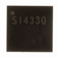
SI4330-B1-FM Silicon Laboratories Inc, SI4330-B1-FM Datasheet - Page 48

SI4330-B1-FM
Manufacturer Part Number
SI4330-B1-FM
Description
IC RCVR ISM 960MHZ 3.6V 20-QFN
Manufacturer
Silicon Laboratories Inc
Type
ISM Receiverr
Specifications of SI4330-B1-FM
Package / Case
20-QFN
Frequency
960MHz
Sensitivity
-118dBm
Data Rate - Maximum
128kbps
Modulation Or Protocol
FSK, GFSK, OOK
Current - Receiving
18.5mA
Data Interface
PCB, Surface Mount
Antenna Connector
PCB, Surface Mount
Voltage - Supply
1.8 V ~ 3.6 V
Operating Temperature
-40°C ~ 85°C
Operating Frequency
240 MHz to 960 MHz
Operating Supply Voltage
3 V
Maximum Operating Temperature
+ 85 C
Minimum Operating Temperature
- 40 C
Mounting Style
SMD/SMT
Supply Current
18.5 mA
Package
20QFN EP
Maximum Data Rate
256 Kbps
Transmission Media Type
Wireless
Power Supply Type
Analog
Typical Operating Supply Voltage
3 V
Minimum Operating Supply Voltage
1.8 V
Maximum Operating Supply Voltage
3.6 V
Lead Free Status / RoHS Status
Lead free / RoHS Compliant
Features
-
Applications
-
Memory Size
-
Lead Free Status / Rohs Status
Lead free / RoHS Compliant
Other names
336-1629-5
SI4330-V2-FM
SI4330-V2-FM
Available stocks
Company
Part Number
Manufacturer
Quantity
Price
Part Number:
SI4330-B1-FM
Manufacturer:
SILICON LABS/èٹ¯ç§‘
Quantity:
20 000
Company:
Part Number:
SI4330-B1-FM-02T
Manufacturer:
SILICON
Quantity:
112
Company:
Part Number:
SI4330-B1-FMR
Manufacturer:
HIROSE
Quantity:
3 200
Part Number:
SI4330-B1-FMR
Manufacturer:
SILICON LABS/èٹ¯ç§‘
Quantity:
20 000
Si4330-B1
8.7. Low Duty Cycle Mode
The Low Duty Cycle Mode is available to automatically wake-up the receiver to check if a valid signal is available.
The basic operation of the low duty cycle mode is demonstrated in the figure below. If a valid preamble or sync
word is not detected the chip will return to sleep mode until the beginning of a new WUT period. If a valid preamble
and sync are detected the receiver on period will be extended for the low duty cycle mode duration (TLDC) to
receive all of the packet. The WUT period must be set in conjunction with the low duty cycle mode duration. The R
value (Reg 14h) is shared between the WUT and the TLDC. The ldc[7:0] bits are located in “Register 19h. Low
Duty Cycle Mode Duration.” The time of the TLDC is determined by the formula below:
R
4
2
TLDC
ldc
7 [
:
] 0
ms
32
.
768
Figure 22. Low Duty Cycle Mode
48
Rev 1.0


