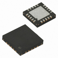
ATA5275-PGPI Atmel, ATA5275-PGPI Datasheet - Page 11

ATA5275-PGPI
Manufacturer Part Number
ATA5275-PGPI
Description
IC TRANSMITTER 125KHZ 20QFN
Manufacturer
Atmel
Datasheet
1.ATA5275-PGPI.pdf
(17 pages)
Specifications of ATA5275-PGPI
Rf Type
TPM
Frequency
125kHz
Package / Case
20-QFN
Lead Free Status / RoHS Status
Lead free / RoHS Compliant
Features
-
Other names
ATA5275-PGPITR
8. Noise and Surge Immunity
9. Electrical Characteristics
4739I–AUTO–01/06
*) Type means: A = 100% tested, B = 100% correlation tested, C = Characterized on samples, D = Design parameter
Notes:
Parameter
Conducted interferences
Note:
No.
1.1
1.2
1.3
1.4
1.5
1.6
1.7
1.8
2.1
2.2
2.3
2.4
1
2
1. 8V < V(DVCC) < 24V; –40 C <
2. Definition of DC
3. I
Parameters
Power Supply
Main supply voltage
Supply current
Standby current
Power-on-reset
threshold voltage
Load dump protection
voltage
Under voltage
detection
Thermal shut down
Protection debounce
filter
Half-bridge Driver Stage
Coil driver resistance
low side driver
Coil driver resistance
high side driver
Driver output rise time
Driver output fall time
1. Test pulse 5: V
VDIO,stby
= 7.5 µA at T
smax
DRV
= 45V
see
amb
Test Conditions
I(VCC) = 10 mA,
including load and line
regulation
without antenna load
Pin DVCC = 13.5V,
T
10% to 90% slope
time,
0% = DVSS,
100% = DVCC
DVCC = 12V
(smooth edges)
10% to 90% slope
time,
0% = DVSS,
100% = DVCC
DVCC = 12V
(smooth edges)
amb
“Application Hints” on page 14
= 90°C
= 90°C
amb
(1)
< 105 C, unless otherwise specified; all values refer to GND
Test Conditions
DVCC,
DVCC
DVCC
DVCC
DVCC
DVSS
ISO 7637-1
DRV,
VCC
VCC
DRV
DRV
DRV
Pin
T
T
Symbol
RDS
VBAT
RDS
VBAT
DRV,RISE
DRV,FALL
I
V
I
TSD
T
V
SUPP
STBY
POR
DEB
CC
ONH
ONL
UV
LD
Min.
150
4.7
3.5
6.0
20
29
10
50
50
2
Typ.
165
100
100
5.0
6.5
0.3
0.3
10
35
31
15
4
Level 4
Value
Max.
180
150
150
5.3
4.5
7.0
0.7
0.7
20
60
35
25
(1)
ATA5275
Unit
mA
µA
o
µs
ns
ns
V
V
V
V
C
Type*
A
A
B
A
A
A
B
A
A
A
D
D
11


