MWI75-06A7T IXYS, MWI75-06A7T Datasheet - Page 4
MWI75-06A7T
Manufacturer Part Number
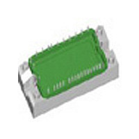
MWI75-06A7T
Description
MOD IGBT SIXPACK RBSOA 600V E2
Manufacturer
IXYS
Datasheet
1.MWI75-06A7.pdf
(4 pages)
Specifications of MWI75-06A7T
Configuration
Three Phase Inverter
Igbt Type
NPT
Voltage - Collector Emitter Breakdown (max)
600V
Vce(on) (max) @ Vge, Ic
2.6V @ 15V, 75A
Current - Collector (ic) (max)
90A
Current - Collector Cutoff (max)
1.3mA
Input Capacitance (cies) @ Vce
3.2nF @ 25V
Power - Max
280W
Input
Standard
Ntc Thermistor
Yes
Mounting Type
Chassis Mount
Package / Case
E2
Channel Type
N
Collector-emitter Voltage
600V
Collector Current (dc) (max)
90A
Gate To Emitter Voltage (max)
±20V
Pin Count
18
Mounting
Screw
Operating Temperature (min)
-40C
Operating Temperature (max)
150C
Operating Temperature Classification
Automotive
Vces, (v)
600
Ic25, Tc = 25°c, Igbt, (a)
90
Ic80, Tc = 80°c, Igbt, (a)
60
Vce(sat), Typ, Tj = 25°c, Igbt, (v)
2.1
Eoff, Typ, Tj = 125°c, Igbt, (mj)
2.5
Rthjc, Max, Igbt, (k/w)
0.44
If25, Tc = 25°c, Diode, (a)
140
If80, Tc = 80°c, Diode, (a)
85
Package Style
E2-Pack
Lead Free Status / RoHS Status
Lead free / RoHS Compliant
Available stocks
Company
Part Number
Manufacturer
Quantity
Price
Company:

Part Number:
MWI75-06A7T
Manufacturer:
IXYS
Quantity:
1 000
Part Number:
MWI75-06A7T
Quantity:
60


IXYS reserves the right to change limits, test conditions and dimensions.
© 2007 IXYS All rights reserved
E
E
I
CM
on
on
10.0
160
120
7.5
5.0
2.5
0.0
mJ
mJ
80
40
10
A
8
6
4
2
0
0
0
0
0
E
Fig. 7 Typ. turn on energy and switching
Fig. 9 Typ. turn on energy and switching
Fig. 11 Reverse biased safe operating area
on
R
T
VJ
G
= 18 Ω
100
= 125°C
10
E
times versus collector current
times versus gate resistor
RBSOA
on
40
200
20
300
80
30
400
t
d(on)
t
r
R
40
I
G
C
500
120
V
V
I
T
V
V
R
T
C
VJ
VJ
CE
GE
CE
GE
G
V
= 300V
= ±15V
= 18Ω
= 75A
= 300V
= ±15V
= 125°C
50
= 125°C
CE
600
A
t
Ω
d(on)
t
160
r
700
60
100
75
50
25
0
100
80
60
40
20
0
ns
ns
V
t
t
Z
E
0.0001
thJC
off
E
0.001
0.01
off
K/W
0.1
mJ
0.00001 0.0001 0.001
mJ
5
4
3
2
1
0
5
4
3
2
1
0
1
0
0
Fig. 8 Typ. turn off energy and switching
Fig.10 Typ. turn off energy and switching
Fig. 12 Typ. transient thermal impedance
10
times versus collector current
times versus gate resistor
40
20
single pulse
0.01
80
30
MWI 75-06 A7
MWI 75-06 A7 T
R
0.1
40
G
I
V
V
R
T
C
120
t
CE
GE
VJ
G
V
V
I
T
C
VJ
CE
GE
= 300V
= 18Ω
= ±15V
= 125°C
= 300V
= ±15V
= 75A
A
= 125°C
50
1
t
E
t
d(off)
f
MWI7506A7
E
off
diode
IGBT
Ω
t
s
off
d(off)
t
f
160
60
10
20070912a
500
ns
400
300
200
100
0
500
400
300
200
100
0
ns
4 - 4
t
t
Related parts for MWI75-06A7T
Image
Part Number
Description
Manufacturer
Datasheet
Request
R

Part Number:
Description:
MOD IGBT SIXPACK RBSOA 600V E2
Manufacturer:
IXYS
Datasheet:
Part Number:
Description:
IGBT MOD TRENCH SIX-PACK E3
Manufacturer:
IXYS
Datasheet:
Part Number:
Description:
IGBT MOD TRENCH SIX-PACK E3
Manufacturer:
IXYS
Datasheet:
Part Number:
Description:
MOD IGBT SIXPACK RBSOA 1200V E3
Manufacturer:
IXYS
Datasheet:

Part Number:
Description:
MOD IGBT SIXPACK RBSOA 1200V E3
Manufacturer:
IXYS
Datasheet:

Part Number:
Description:
HiPerFET Power MOSFETs
Manufacturer:
IXYS Corporation
Datasheet:
Part Number:
Description:
J-K-Type Flip-Flop
Manufacturer:
IXYS Corporation
Datasheet:
Part Number:
Description:
HiPerRF Power MOSFETs
Manufacturer:
IXYS Corporation
Datasheet:
Part Number:
Description:
Rectifier Module for Three Phase Power Factor Correction
Manufacturer:
IXYS Corporation
Datasheet: