CM100RX-12A Powerex Inc, CM100RX-12A Datasheet - Page 2
CM100RX-12A
Manufacturer Part Number
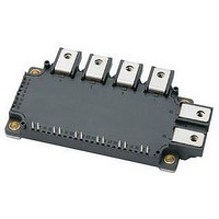
CM100RX-12A
Description
IGBT MOD 7PAC 600V 100A NX SER
Manufacturer
Powerex Inc
Series
IGBTMOD™r
Type
IGBTr
Datasheet
1.CM100RX-12A.pdf
(6 pages)
Specifications of CM100RX-12A
Configuration
Three Phase Inverter with Brake
Voltage - Collector Emitter Breakdown (max)
600V
Vce(on) (max) @ Vge, Ic
2.1V @ 15V, 100A
Current - Collector (ic) (max)
100A
Current - Collector Cutoff (max)
1mA
Input Capacitance (cies) @ Vce
13.3nF @ 10V
Power - Max
400W
Input
Standard
Ntc Thermistor
Yes
Mounting Type
Chassis Mount
Package / Case
Module
Dc Collector Current
100A
Collector Emitter Voltage Vces
600V
Power Dissipation Pd
10mW
Collector Emitter Voltage V(br)ceo
600V
Operating Temperature Range
-40°C To +150°C
No. Of Pins
23
Voltage
600V
Current
100A
Circuit Configuration
7-PAC
Rohs Compliant
Yes
Recommended Gate Driver
M57959L
Recommended Dc To Dc Converter
VLA106-15242
Lead Free Status / RoHS Status
Lead free / RoHS Compliant
For Use With
BG2B-5015 - KIT DEV BOARD 2CN 5A FOR IGBTBG2B-3015 - KIT DEV BOARD 2CN 3A FOR IGBTBG2B-1515 - KIT DEV BOARD 1.5A FOR IGBTBG2A-NF - KIT DEV BOARD FOR IGBT
Igbt Type
-
Lead Free Status / RoHS Status
Lead free / RoHS Compliant, Lead free / RoHS Compliant


2
Powerex, Inc., 173 Pavilion Lane, Youngwood, Pennsylvania 15697 (724) 925-7272
CM100RX-12A
Six IGBTMOD™ + Brake NX-Series Module
100 Amperes/600 Volts
Absolute Maximum Ratings, T
Characteristics
Power Device Junction Temperature
Storage Temperature
Mounting Torque, M5 Mounting Screws
Mounting Torque, M5 Main Terminal Screws
Module Weight (Typical)
Baseplate Flatness, On Centerline X, Y (See Below)
Isolation Voltage, AC 1 minute, 60Hz Sinusoidal
Inverter Sector
Collector-Emitter Voltage (G-E Short)
Gate-Emitter Voltage (C-E Short)
Collector Current (T
Peak Collector Current (Pulse)
Emitter Current (T
Peak Emitter Current
Maximum Collector Dissipation (T
Brake Sector
Collector-Emitter Voltage (G-E Short)
Gate-Emitter Voltage (C-E Short)
Collector Current (T
Peak Collector Current (Pulse)
Maximum Collector Dissipation (T
Repetitive Peak Reverse Voltage (Clamp Diode Part)
Forward Current (T
Forward Current (Pulse)
*1 Case temperature (T
*2 I
*3 Pulse width and repetition rate should be such that device junction temperature (T
*4 Junction temperature (T
BASEPLATE FLATNESS
MEASUREMENT POINT
I
E
F
, I
, I
FM
EM
, I
, V
RRM
EC
, t
, V
rr
FM
and Q
C
C
and V
C
C
= 25°C)
C
*3
= 25°C)
X
= 75°C)
= 97°C)
) and heatsink temperature (T
rr
HEATSINK SIDE
– : CONCAVE
+ : CONVEX
j
) should not increase beyond T
*3
represent ratings and characteristics of the anti-parallel, emitter-to-collector free-wheel diode (FWDi).
RRM
*1
*1
represent ratings and characteristics of the clamp diode.
*1
*1
Y
*3
*3
C
C
= 25°C)
= 25°C)
j
= 25°C unless otherwise specified
*1*4
*1*4
f
) are defined on the surface of the baseplate and heatsink at just under the chip.
j(max)
rating.
CHIP LOCATION (TOP VIEW)
Chip Location (Top View)
24.8
29.4
32.2
36.8
0
IGBT
j
) does not exceed T
FWDi
35
36
U
U
P
34
P
NTC Thermistor
33 32 31 30 29 28 27 26 25 24 23 22
U
U
1
N
N
V
Symbol
V
V
V
V
I
I
V
RRM
T
EM
I
I
FM
V
I
I
V
P
P
CES
GES
CES
GES
—
—
—
—
CM
E
CM
ISO
I
I
F
T
P
stg
j(max)
P
C
C
C
C
*2
*2
j
*2
*2
V
V
N
*2
N
2
rating.
Dimensions in mm (Tolerance: ±1mm)
21 20 19 18 17 16 15 14 13
W
3
W
P
P
W
W
CM100RX-12A
N
N
-40 to 150
-40 to 125
±0 ~ +100
Br
Th
4
2500
330
600
±20
100
200
100
200
400
600
±20
100
280
600
100
31
31
50
50
Br
12
11
10
9
8
7
6
5
0
21.3
30.4
41.2
Amperes
Amperes
Amperes
Amperes
Amperes
Amperes
Amperes
Amperes
Grams
Watts
Watts
Units
Volts
Volts
Volts
Volts
Volts
Volts
in-lb
in-lb
µm
°C
°C
Rev. 3/09
Related parts for CM100RX-12A
Image
Part Number
Description
Manufacturer
Datasheet
Request
R

Part Number:
Description:
IGBT MOD 7PAC 1200V 100A NX SER
Manufacturer:
Powerex Inc
Datasheet:

Part Number:
Description:
IGBT MODULE NX-SERIES 7-PAC DP 1200 100
Manufacturer:
Powerex Inc
Datasheet:


Part Number:
Description:
RF Devices / Rectifier Diodes
Manufacturer:
Bharat Electronics Ltd
Part Number:
Description:
Molded Mini-dyad
Manufacturer:
ETC-unknow
Datasheet:
Part Number:
Description:
Plug Connector
Manufacturer:
DDK Ltd.
Datasheet:
Part Number:
Description:
Molded Mini-DYAD
Manufacturer:
CLARE [Clare, Inc.]
Datasheet:
Part Number:
Description:
One-Touch Locking Style Small Sized Circular Connectors
Manufacturer:
DDK [DDK Ltd.]
Datasheet:

Part Number:
Description:
INDUCTOR CHIP SMD
Manufacturer:
Bourns Inc.
Datasheet:
Part Number:
Description:
INDUCTOR CHIP SMD
Manufacturer:
Bourns Inc.
Datasheet:
Part Number:
Description:
INDUCTOR CHIP SMD
Manufacturer:
Bourns Inc.
Datasheet:
Part Number:
Description:
INDUCTOR CHIP SMD
Manufacturer:
Bourns Inc.
Datasheet:
Part Number:
Description:
INDUCTOR CHIP SMD
Manufacturer:
Bourns Inc.
Datasheet:
Part Number:
Description:
INDUCTOR CHIP SMD
Manufacturer:
Bourns Inc.
Datasheet: