CM150TX-24S Powerex Inc, CM150TX-24S Datasheet - Page 4
CM150TX-24S
Manufacturer Part Number
CM150TX-24S
Description
IGBT MOD 1200V 150A 6PAC NX SER
Manufacturer
Powerex Inc
Series
IGBTMOD™r
Type
6-PACr
Datasheet
1.CM150TX-24S.pdf
(4 pages)
Specifications of CM150TX-24S
Featured Product
6th Generation NX-S Series IGBTs
Configuration
Three Level Inverter
Voltage - Collector Emitter Breakdown (max)
1200V
Vce(on) (max) @ Vge, Ic
2.15V @ 15V, 150A
Current - Collector (ic) (max)
150A
Current - Collector Cutoff (max)
1mA
Input Capacitance (cies) @ Vce
15nF @ 10V
Power - Max
1150W
Input
Standard
Ntc Thermistor
Yes
Mounting Type
Chassis Mount
Package / Case
Module
Module Configuration
Six
Dc Collector Current
150A
Collector Emitter Voltage Vces
1.2kV
Power Dissipation Pd
1.15kW
Operating Temperature Range
-40°C To +150°C
Peak Reflow Compatible (260 C)
Yes
Rohs Compliant
Yes
Leaded Process Compatible
Yes
Prx Availability
RequestQuote
Distributorinventory
View
Voltage
1200V
Current
150A
Circuit Configuration
6-Pac
Recommended Gate Driver
M57159L
Recommended Dc To Dc Converter
VLA106-15242
Lead Free Status / RoHS Status
Lead free / RoHS Compliant
Igbt Type
-
Lead Free Status / RoHS Status
Lead free / RoHS Compliant
Other names
835-1122
Available stocks
Company
Part Number
Manufacturer
Quantity
Price
Company:

Part Number:
CM150TX-24S
Manufacturer:
Powerex Inc
Quantity:
135
Company:
Part Number:
CM150TX-24S
Manufacturer:
MITSUBISH
Quantity:
1 000
Part Number:
CM150TX-24S
Manufacturer:
MIT
Quantity:
20 000


4
Powerex, Inc., 173 Pavilion Lane, Youngwood, Pennsylvania 15697 (724) 925-7272 www.pwrx.com
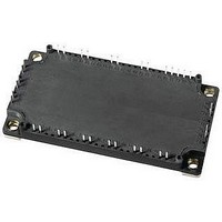
CM150TX-24S
Six IGBTMOD™ NX-S Series Module
150 Amperes/1200 Volts
NTC Thermistor Sector, T
Characteristics
Zero Power Resistance
Deviation of Resistance
B Constant
Power Dissipation
Module, T
Characteristics
Lead Resistance (Main Terminals-Chip)
Contact Thermal Resistance
(Case to Heatsink)
*1 Case temperature (T
*2 Typical value is measured by using thermally conductive grease of λ = 0.9 [W/(m • K)].
*9 B
300
250
200
150
100
(25/50)
30
25
20
15
10
50
0
5
0
SATURATION VOLTAGE CHARACTERISTICS
0
0
= In(
V
V
R
T
Inductive Load
V
CC
GE
j
G
GE
SATURATION VOLTAGE, V
0.5
= 125°C
COLLECTOR CURRENT, I
= 5.1Ω
R
R
(INVERTER PART - TYPICAL)
(INVERTER PART - TYPICAL)
= 600V
= ±15V
= 15V
j
50
T
T
T
E
E
E
25
= 25°C unless otherwise specified
COLLECTOR CURRENT
j
j
j
on
off
rr
COLLECTOR-EMITTER
SWITCHING LOSS VS.
)/(
= 25°C
= 125°C
= 150°C
1.0
COLLECTOR-EMITTER
T
C
50
25
1
) and heatsink temperature (T
1.5
–
T
1
50
2.0
) R
T
25
C
*1
25
CE(sat)
100
, (AMPERES)
; Resistance at Absolute Temperature T
2.5
= 25 [°C] + 273.15 = 298.15 [K], T
, (VOLTS )
j
= 25°C unless otherwise specified
3.0
150
3.5
f
) measured point is just under the chips.
B
Symbol
Symbol
R
R
∆R/R
(25/50)
P
th(c-f)
lead
R
25
300
250
200
150
100
70
60
50
40
30
20
10
50
0
0
0
0
50
EMITTER-COLLECTOR VOLTAGE, V
V
V
I
T
Inductive Load
V
C
j
GE
CC
GE
= 50 [°C] + 273.15 = 323.15 [K]
= 150°C
= 150A
25
FORWARD CHARACTERISTICS
10
0.5
(INVERTER PART - TYPICAL)
(INVERTER PART - TYPICAL)
= 600V
= ±15V
= 0V
T
T
T
[K], R
j
j
j
GATE RESISTANCE, R
= 25°C
= 125°C
= 150°C
SWITCHING LOSS VS.
FREE-WHEEL DIODE
GATE RESISTANCE
1.0
20
50
Approximate by Equation
T
; resistance at Absolute Temperature T
C
Thermal Grease Applied
= 100°C, R
T
1.5
30
C
Test Conditions
Test Conditions
E
E
E
(Per 1 Module)
= 25°C (Per Switch)
T
T
on
off
rr
C
C
2.0
40
= 25°C
= 25°C
G
, (Ω)
EC
100
, (VOLTS)
2.5
50
= 493Ω
3.0
60
*2
*9
50
[K],
30
25
20
15
10
70
60
50
40
30
20
10
5
0
0
0
0
Min.
4.85
Min.
–7.3
V
V
R
T
Inductive Load
V
V
I
T
Inductive Load
C
—
—
—
—
CC
GE
j
CC
GE
j
G
= 150°C
= 125°C
= 150A
COLLECTOR CURRENT, I
= 5.1Ω
10
(INVERTER PART - TYPICAL)
= 600V
= ±15V
(INVERTER PART - TYPICAL)
= 600V
= ±15V
E
E
E
COLLECTOR CURRENT
on
off
rr
GATE RESISTANCE, R
SWITCHING LOSS VS.
SWITCHING LOSS VS.
GATE RESISTANCE
20
50
0.015
3375
5.00
Typ.
Typ.
—
—
—
30
E
E
E
on
off
rr
C
100
Max.
Max.
5.15
, (AMPERES)
+7.8
40
1.8
—
10
—
G
, (Ω)
50
04/10 Rev. 0
Units
Units
mW
K/W
mΩ
150
kΩ
60
%
K
Related parts for CM150TX-24S
Image
Part Number
Description
Manufacturer
Datasheet
Request
R

Part Number:
Description:
SWITCH REED 15-25AT SPST SMD
Manufacturer:
Coto Technology
Datasheet:
Part Number:
Description:
SWITCH REED 15-20AT SPST SMD
Manufacturer:
Coto Technology
Datasheet:
Part Number:
Description:
SWITCH REED 10-30AT SPST SMD
Manufacturer:
Coto Technology
Datasheet:
Part Number:
Description:
SWITCH REED 20-25AT SPST SMD
Manufacturer:
Coto Technology
Datasheet:
Part Number:
Description:
SWITCH REED 10-20AT SPST SMD
Manufacturer:
Coto Technology
Datasheet:
Part Number:
Description:
SWITCH REED 10-15AT SPST SMD
Manufacturer:
Coto Technology
Datasheet:


Part Number:
Description:
Switch Fabric, Tip-Over Switches
Manufacturer:
Comus Group of Companies

Part Number:
Description:
Manufacturer:
Powerex Inc
Datasheet:
Part Number:
Description:
Manufacturer:
Powerex Inc
Datasheet:
Part Number:
Description:
Manufacturer:
Powerex Inc
Datasheet:
Part Number:
Description:
Manufacturer:
Powerex Inc
Datasheet:
Part Number:
Description:
Manufacturer:
Powerex Inc
Datasheet:
Part Number:
Description:
Manufacturer:
Powerex Inc
Datasheet: