PS21961-4 Powerex Inc, PS21961-4 Datasheet - Page 6
PS21961-4
Manufacturer Part Number
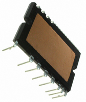
PS21961-4
Description
MOD IPM 600V 3A SUPERMINI DIP
Manufacturer
Powerex Inc
Series
Intellimod™r
Type
IGBTr
Datasheet
1.PS21961-4.pdf
(7 pages)
Specifications of PS21961-4
Configuration
3 Phase
Current
3A
Voltage
600V
Voltage - Isolation
1500VDC
Package / Case
PCB Module
Dc Collector Current
3A
Collector Emitter Voltage Vces
600V
Power Dissipation Pd
21.3W
Collector Emitter Voltage V(br)ceo
600V
Operating Temperature Range
-20°C To +100°C
No. Of Pins
25
Lead Free Status / RoHS Status
Lead free / RoHS Compliant
Other names
835-1039


Powerex, Inc., 173 Pavilion Lane, Youngwood, Pennsylvania 15697-1800 (724) 925-7272
PS21961-4, PS21961-4A, PS21961-4C
Intellimod™ Module
Dual-In-Line Intelligent Power Module
3 Amperes/600 Volts
Protection Function Timing Diagrams
THE SHUNT RESISTOR
Short-Circuit Protection (Lower-arms only with the external shunt resistor and RC filter)
Under-Voltage Protection (Lower-side, UV D )
INTERNAL IGBT GATE
OUTPUT CURRENT I C
OUTPUT CURRENT I C
SENSE VOLTAGE OF
CONTROL SUPPLY
FAULT OUTPUT F O
FAULT OUTPUT F O
CONTROL INPUT
CONTROL INPUT
CIRCUIT STATE
CIRCUIT STATE
LOWER-ARMS
A1: Normal operation – IGBT turn on and conducting current.
A2: Short-circuit current detected (SC trigger).
A3: IGBT gate hard interrupted.
A4: IGBT turn off.
A5: F O output with a fixed pulse width of t FO(min) = 20µs.
A6: Input “L” – IGBT off.
A7: Input “H” – IGBT on is blocked during the F O output period.
A8: IGBT stays in off state.
B1: Control supply voltage rise – After the voltage level reaches UV Dr , the drive circuit begins to work
B2 : Normal operation – IGBT turn on and conducting current.
B3: Under-voltage trip (UV Dt ).
B4: IGBT turn off regardless of the control input level.
B5: F O output during under-voltage period, however, the minimum pulse width is 20µs.
B6: Under-voltage reset (UV Dr ).
B7: Normal operation – IGBT turn on and conducting current.
PROTECTION
PROTECTION
VOLTAGE V D
at the rising edge of the next input signal.
UV Dr
RESET
A1
B1
SC
A2
SET
UV Dt
A5
B2
A3
A4
SET
B4
CR CIRCUIT TIME CONTAINS
DELAY (NOTE)
B3
SC REFERENCE VOLTAGE
A6
B5
RESET
A7
B6
RESET
A8
B7
Rev. 03/07
Related parts for PS21961-4
Image
Part Number
Description
Manufacturer
Datasheet
Request
R

Part Number:
Description:
Manufacturer:
Powerex Inc
Datasheet:
Part Number:
Description:
Manufacturer:
Powerex Inc
Datasheet:
Part Number:
Description:
Manufacturer:
Powerex Inc
Datasheet:
Part Number:
Description:
Manufacturer:
Powerex Inc
Datasheet:
Part Number:
Description:
Manufacturer:
Powerex Inc
Datasheet:
Part Number:
Description:
Manufacturer:
Powerex Inc
Datasheet:
Part Number:
Description:
Manufacturer:
Powerex Inc
Datasheet:
Part Number:
Description:
Manufacturer:
Powerex Inc
Datasheet:
Part Number:
Description:
Manufacturer:
Powerex Inc
Datasheet:
Part Number:
Description:
Manufacturer:
Powerex Inc
Datasheet:
Part Number:
Description:
Manufacturer:
Powerex Inc
Datasheet:
Part Number:
Description:
Manufacturer:
Powerex Inc
Datasheet:
Part Number:
Description:
Manufacturer:
Powerex Inc
Datasheet:
Part Number:
Description:
Manufacturer:
Powerex Inc
Datasheet: