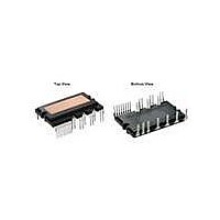
FPAB30BH60B Fairchild Semiconductor, FPAB30BH60B Datasheet - Page 5

FPAB30BH60B
Manufacturer Part Number
FPAB30BH60B
Description
MOD SPM 600V 30A SPM27-IC
Manufacturer
Fairchild Semiconductor
Series
SPM™r
Type
IGBTr
Datasheet
1.FPAB30BH60B.pdf
(12 pages)
Specifications of FPAB30BH60B
Configuration
1 Phase
Current
30A
Voltage
600V
Voltage - Isolation
2500Vrms
Package / Case
SPM27IC
Collector- Emitter Voltage Vceo Max
600 V
Continuous Collector Current At 25 C
30 A
Gate-emitter Leakage Current
250 uA
Power Dissipation
104 W
Maximum Operating Temperature
+ 125 C
Minimum Operating Temperature
- 40 C
Mounting Style
Through Hole
Lead Free Status / RoHS Status
Lead free / RoHS Compliant
Available stocks
Company
Part Number
Manufacturer
Quantity
Price
Company:
Part Number:
FPAB30BH60B
Manufacturer:
Fairchild Semiconductor
Quantity:
135
©2010 Fairchild Semiconductor Corporation
Electrical Characteristics
Converter Part
Note
1. t
Electrical Characteristics
Control Part
Note
2. The fault-out pulse width t
3. T
IGBT saturation voltage
FRD forward voltage
Rectifier forward voltage
Switching Times
Collector - emitter
Leakage Current
Quiescent V
rent
Fault Output Voltage
Over Current Trip Level
Supply Circuit Under-
Voltage Protection
Fault-out Pulse Width
ON Threshold Voltage
OFF Threshold Voltage
Resistance of Thermistor
internally. For the detailed information, please see Fig. 4
ON
TH
and t
is the temperature of know case temperature(Tc), please make the experiment considering your application.
OFF
Item
Item
include the propagation delay time of the internal drive IC. t
CC
V
IN
Supply Cur-
V
I
CE
C
FOD
10% of I
depends on the capacitance value of C
90% of I
C
t
ON
Symbol
V
100% of I
V
UV
UV
V
I
C
V
V
IN(OFF)
(a) Turn-on
QCCL
SC(ref)
t
IN(ON)
R
Symbol
FOD
V
FOH
FOL
t
t
CCD
CCR
TH
C(OFF)
CE(sat)
C(ON)
t
I
V
V
t
OFF
CES
ON
t
I
C
FF
FR
rr
rr
I
rr
V
V
V
V
Detection Level
Reset Level
C
Applied between IN - COM
@ T
@ T
t
C(ON)
Fig. 4. Switching Time Definition
(T
CC
SC
SC
CC
FOD
t
rr
J
TH
TH
= 0V, V
= 1V, V
= 15V, IN = 0V V
= 15V
= 25°C, Unless Otherwise Specified)
V
I
I
V
V
(Note 1)
V
= 33nF (Note 2)
F
F
CC
PN
IN
CE
= 25°C (Note3, Fig. 9)
= 100°C (Note3, Fig. 9)
= 30A
= 30A
120% of I
= 0V « 5V, Inductive Load
=15V, V
= 400V, V
= V
15% of V
FO
FO
CES
FOD
Circuit: 4.7kW to 5V Pull-up
Circuit: 4.7kW to 5V Pull-up
C
C(ON)
CE
according to the following approximate equation : C
IN
Condition
and t
CC
= 5V; I
Condition
= 15V, I
CC
C(OFF)
V
IN
- COM
C
V
are the switching time of IGBT itself under the given gate driving condition
I
C
CE
=30A
C
15% of V
=30A
t
OFF
CE
(b) Turn-off
t
C(OFF)
Min.
Min.
0.45
10.7
11.2
4.5
1.4
2.8
-
-
-
-
-
-
-
-
-
-
-
-
-
-
-
FOD
= 18.3 x 10
Typ.
10% of I
500
200
420
100
2.2
1.9
1.2
60
Typ.
11.9
12.4
47.0
7
-
0.5
1.8
2.9
-
-
-
-
-
C
-6
Max.
250
Max.
2.8
2.6
1.5
0.55
13.0
13.2
x t
0.8
2.0
0.8
26
-
-
-
-
-
-
-
-
-
-
FOD
[F]
Unit
Unit
mA
ns
ns
ns
ns
ns
mA
ms
kW
kW
V
V
V
A
V
V
V
V
V
V
V


