PM25CLA120 Powerex Inc, PM25CLA120 Datasheet - Page 3
PM25CLA120
Manufacturer Part Number
PM25CLA120
Description
MOD IPM L-SER 6PAC 1200V 25A
Manufacturer
Powerex Inc
Series
Intellimod™r
Type
IGBTr
Datasheet
1.PM25CLA120.pdf
(6 pages)
Specifications of PM25CLA120
Configuration
3 Phase Inverter
Current
25A
Voltage
1200V
Voltage - Isolation
2500VDC
Package / Case
Module
Transistor Polarity
N Channel
Dc Collector Current
25A
Collector Emitter Voltage Vces
1.2kV
Power Dissipation Pd
116W
Collector Emitter Voltage V(br)ceo
1.2kV
Operating Temperature Range
-20°C To +150°C
Prx Availability
RequestQuote
Circuit Configuration
6-Pac
Package
120x55mm - A
Rohs Compliant
Yes
Recommended Accessory
BP7B-LS
Lead Free Status / RoHS Status
Lead free / RoHS Compliant
For Use With
BP7B-LS - KIT DEV INTERFACE FOR IPMBP7A-LS - KIT DEV INTERFACE FOR IPM
Lead Free Status / RoHS Status
Lead free / RoHS Compliant, Lead free / RoHS Compliant
Available stocks
Company
Part Number
Manufacturer
Quantity
Price
Company:

Part Number:
PM25CLA120
Manufacturer:
IXYS
Quantity:
530
Part Number:
PM25CLA120
Manufacturer:
MIT
Quantity:
20 000
Part Number:
PM25CLA120
Quantity:
60


Powerex, Inc., 200 E. Hillis Street, Youngwood, Pennsylvania 15697-1800 (724) 925-7272
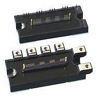
PM25CLA120
Intellimod™ L-Series
Three Phase IGBT Inverter
25 Amperes/1200 Volts
Electrical and Mechanical Characteristics, T
Characteristics
IGBT Inverter Sector
Collector-Emitter Cutoff Current
Diode Forward Voltage
Collector-Emitter Saturation Voltage
Inductive Load Switching Times
Control Sector
Short Circuit Trip Level
Short Circuit Current Delay Time
Over Temperature Protection
(Detect T
Supply Circuit Under-voltage Protection
(-20 ≤ T
Circuit Current
Input ON Threshold Voltage
Input OFF Threshold Voltage
Fault Output Current*
Fault Output Pulse Width*
*Fault output is given only when the internal SC, OT and UV protections schemes of either upper or lower devide operate to protect it.
T
C
Measurement Point
j
Y
≤ 125°C)
j
of IGBT Chip)
X
BOTTOM VIEW
Axis
Arm
Y
X
V
Symbol
t
V
V
I
off(SC)
I
t
t
CE(sat)
I
FO(H)
C(on)
C(off)
OT
UV
FO(L)
V
th(on)
th(off)
CES
t
SC
OT
UV
t
t
t
I
FO
on
off
EC
rr
D
R
R
IGBT FWDi IGBT FWDi IGBT FWDi IGBT FWDi IGBT FWDi IGBT FWDi
29.0
-7.1
UP
j
= 25°C unless otherwise specified
29.3
1.5
V
P
V
V
-V
V
-I
CE
V
D
V
V
CE
C
-20°C ≤ T
D
VPC
D
D
= 15V, V
Applied between U
64.0
V
-7.1
= 25A, V
= V
= 15V, V
= 15V, V
= 15V, V
D
= V
V
V
V
, W
= 15V, V
CC
D
D
CES
VP
CES
Test Conditions
= 15V, V
= 15V, V
P
65.5
= 600V, I
Reset Level
Reset Level
-V
2.0
T
T
CIN
, V
j
V
Trip Level
Trip Level
V
T
, V
CIN
≤ 125°C, V
CIN
j
j
CIN
CIN
WPC
j
D
D
= 125°C
= 125°C
D
= 25°C
D
CIN
= 15V, V
= 15V
= 15V
= 15V, T
= 15V, V
= 15V, V
= 15V, T
= 0V, I
= 0V, I
85.6
-7.1
CIN
CIN
, U
= 0 ⇔ 15V
C
N
WP
= 25A
= 15V
= 15V
P
- V
-V
D
C
C
XP1
85.9
j
D
N1
N
2.0
j
= 15V
UPC
= 25A,
= 25A,
= 125°C
= 25°C
- W
= 15V
-V
-V
,
NC
XPC
N
-V
37.8
5.1
NC
UN
37.5
-4.5
Min.
11.5
135
0.5
1.2
1.7
1.0
50
—
—
—
—
—
—
—
—
—
—
—
—
—
—
—
—
55.2
5.1
12.0
12.5
145
125
Typ.
2.5
1.8
1.9
1.0
0.5
0.4
2.0
0.7
0.2
1.5
2.0
1.8
15
10
VN
—
—
—
—
5
55.7
-4.5
Max.
12.5
0.01
155
1.0
3.5
2.3
2.4
2.5
0.8
1.0
3.0
1.2
1.8
2.3
75.8
10
—
—
—
—
25
10
15
—
5.1
WN
Amperes
75.3
-4.5
Units
Volts
Volts
Volts
Volts
Volts
Volts
Volts
mA
mA
mA
mA
mA
mA
ms
µs
µs
µs
µs
µs
µs
°C
°C
3
Related parts for PM25CLA120
Image
Part Number
Description
Manufacturer
Datasheet
Request
R

Part Number:
Description:
Power Module Power Modules Standard Power - Switchbox Ac/dc . Switchbox Pm25 Series Dc-dc Converter
Manufacturer:
Powerbox
Datasheet:
Part Number:
Description:
25-28 WATTS SINGLE & MULTIPLE OUTPUT AC/DC MEDICAL
Manufacturer:
POWERBOX [Powerbox]
Datasheet:

Part Number:
Description:
Manufacturer:
Powerex Inc
Datasheet:
Part Number:
Description:
Manufacturer:
Powerex Inc
Datasheet:
Part Number:
Description:
Manufacturer:
Powerex Inc
Datasheet:
Part Number:
Description:
Manufacturer:
Powerex Inc
Datasheet:
Part Number:
Description:
Manufacturer:
Powerex Inc
Datasheet:
Part Number:
Description:
Manufacturer:
Powerex Inc
Datasheet:
Part Number:
Description:
Manufacturer:
Powerex Inc
Datasheet:
Part Number:
Description:
Manufacturer:
Powerex Inc
Datasheet:
Part Number:
Description:
Manufacturer:
Powerex Inc
Datasheet:
Part Number:
Description:
Manufacturer:
Powerex Inc
Datasheet:
Part Number:
Description:
Manufacturer:
Powerex Inc
Datasheet:
Part Number:
Description:
Manufacturer:
Powerex Inc
Datasheet: