VSKT500-12 Vishay, VSKT500-12 Datasheet - Page 4
VSKT500-12
Manufacturer Part Number
VSKT500-12
Description
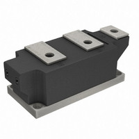
SCR DBL 2SCR 1200V 500A MAGNAPAK
Manufacturer
Vishay
Datasheet
1.VSKH500-12.pdf
(8 pages)
Specifications of VSKT500-12
Structure
Series Connection - All SCRs
Number Of Scrs, Diodes
2 SCRs
Voltage - Off State
1200V
Current - Gate Trigger (igt) (max)
200mA
Current - On State (it (av)) (max)
500A
Current - On State (it (rms)) (max)
785A
Current - Non Rep. Surge 50, 60hz (itsm)
17800A, 18700A
Current - Hold (ih) (max)
500mA
Mounting Type
Chassis Mount
Package / Case
SUPER MAGN-A-PAK
Rated Repetitive Off-state Voltage Vdrm
1200 V
Off-state Leakage Current @ Vdrm Idrm
100 mA
Holding Current (ih Max)
500 mA
Mounting Style
Screw
Breakover Current Ibo Max
18700 A
Gate Trigger Current (igt)
200 mA
Gate Trigger Voltage (vgt)
3 V
Repetitive Peak Forward Blocking Voltage
1200 V
Lead Free Status / RoHS Status
Contains lead / RoHS non-compliant
Other names
*IRKT500-12
IRKT500-12
IRKT500-12
IRKT500-12
IRKT500-12


VSKT500-..PbF, VSKH500-..PbF, VSKL500-..PbF
Vishay Semiconductors
www.vishay.com
4
700
600
500
400
300
200
100
130
120
110
100
Fig. 3 - On-State Power Loss Characteristics
130
120
110
100
90
80
70
60
90
80
70
60
0
Fig. 1 - Current Ratings Characteristics
Fig. 2 - Current Ratings Characteristics
0 100 200 300 400 500 600 700 800 900
0
0
R MS Limit
100
180°
120°
Average On-state Current (A)
Average On-state Current (A)
Average On-state Current (A)
100
90°
60°
30°
30°
30°
200
60°
200
DiodesAmericas@vishay.com, DiodesAsia@vishay.com,
VSK.500.. S eries
R
90°
VSK.500.. S eries
R
thJC
60°
For technical questions within your region, please contact one of the following:
thJC
120°
300
(DC) = 0.065 K/ W
90°
(DC) = 0.065 K/ W
Conduc tion Angle
Conduc tion Angle
Conduction Period
300
180°
VSK.500.. S eries
Per Junction
T = 130°C
J
400
120°
(SUPER MAGN-A-PAK Power Modules), 500 A
400
DC
180°
500
Thyristor/Diode and Thyristor/Thyristor
500
600
16000
15000
14000
13000
12000
11000
10000
18000
16000
14000
12000
10000
9000
8000
7000
Fig. 5 - Maximum Non-Repetitive Surge Current
Fig. 6 - Maximum Non-Repetitive Surge Current
8000
6000
1000
Number Of Equal Amplitude Half Cycle Current Pulses (N)
DiodesEurope@vishay.com
900
800
700
600
500
400
300
200
100
Fig. 4 - On-State Power Loss Characteristics
0
0.01
1
0
RMS Limit
Of Cond uc tion Ma y Not Be Maintained.
VSK.500.. S eries
Per Junction
VSK.500.. S eries
Per Junction
At Any Rated Loa d Cond ition And With
Ma ximum Non R ep etitive S urge Current
Rated V
100 200 300 400 500 600 700 800
Average On-state Current (A)
Versus Pulse T rain Dura tion. Control
180°
120°
DC
90°
60°
30°
Pulse T rain Duration (s)
RRM
Ap p lied Following S urge.
No Voltage Reapplied
Rated V
0.1
10
Conduction Period
VSK.500.. S eries
Per Junc tion
T = 130°C
J
@ 60 Hz 0.0083 s
@ 50 Hz 0.0100 s
Initial T = 130°C
Initial T = 130°C
RRM
Document Number: 94420
Reapplied
J
J
Revision: 02-Jul-10
100
1
Related parts for VSKT500-12
Image
Part Number
Description
Manufacturer
Datasheet
Request
R

Part Number:
Description:
SCR DBL 2SCR 800V 500A MAGNAPAK
Manufacturer:
Vishay
Datasheet:
Part Number:
Description:
SCR DBL 2SCR 1400V 500A MAGNAPAK
Manufacturer:
Vishay
Datasheet:
Part Number:
Description:
SCR DBL 2SCR 1600V 500A MAGNAPAK
Manufacturer:
Vishay
Datasheet:

Part Number:
Description:
SCR Modules 500 Amp 1200 Volt 785 Amp IT(RMS)
Manufacturer:
Vishay
Part Number:
Description:
SCR Modules 500 Amp 1400 Volt 785 Amp IT(RMS)
Manufacturer:
Vishay
Part Number:
Description:
SCR Modules 500 Amp 800 Volt 785 Amp IT(RMS)
Manufacturer:
Vishay
Part Number:
Description:
SCR Modules 500 Amp 1600 Volt 785 Amp IT(RMS)
Manufacturer:
Vishay

Part Number:
Description:
Thyristor/Diode and Thyristor/Thyristor
Manufacturer:
Vishay Siliconix
Datasheet:
Part Number:
Description:
357-036-542-201 CARDEDGE 36POS DL .156 BLK LOPRO
Manufacturer:
Vishay
Datasheet:
Part Number:
Description:
357-036-542-201 CARDEDGE 36POS DL .156 BLK LOPRO
Manufacturer:
Vishay
Datasheet:
Part Number:
Description:
357-036-542-201 CARDEDGE 36POS DL .156 BLK LOPRO
Manufacturer:
Vishay
Datasheet:
Part Number:
Description:
357-036-542-201 CARDEDGE 36POS DL .156 BLK LOPRO
Manufacturer:
Vishay
Datasheet:
Part Number:
Description:
357-036-542-201 CARDEDGE 36POS DL .156 BLK LOPRO
Manufacturer:
Vishay
Datasheet:
Part Number:
Description:
357-036-542-201 CARDEDGE 36POS DL .156 BLK LOPRO
Manufacturer:
Vishay
Datasheet:
Part Number:
Description:
357-036-542-201 CARDEDGE 36POS DL .156 BLK LOPRO
Manufacturer:
Vishay
Datasheet: