B614F-2T Crydom Co., B614F-2T Datasheet
B614F-2T
Manufacturer Part Number
B614F-2T
Description
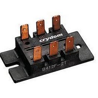
MOD DIODE SCR 42.5A 480V .250"QC
Manufacturer
Crydom Co.
Specifications of B614F-2T
Structure
Bridge, Single Phase - SCRs/Diodes (Layout 1)
Number Of Scrs, Diodes
2 SCRs, 2 Diodes
Voltage - Off State
1200V
Current - Gate Trigger (igt) (max)
80mA
Current - On State (it (rms)) (max)
42.5A (DC)
Current - Non Rep. Surge 50, 60hz (itsm)
600A @ 60Hz
Mounting Type
Chassis Mount
Package / Case
Module
Peak Repetitive Off-state Voltage, Vdrm
1.2kV
Gate Trigger Current Max, Igt
80mA
Current It Av
42.5A
Peak Non Rep Surge Current Itsm 50hz
600A
Gate Trigger Voltage Max Vgt
3V
Lead Free Status / RoHS Status
Lead free / RoHS Compliant
Current - Hold (ih) (max)
-
Current - On State (it (av)) (max)
-
Lead Free Status / RoHS Status
Lead free / RoHS Compliant, Lead free / RoHS Compliant


B-2T, B-2 Series
AVAILABLE OPTIONS
ELECTRICAL SPECIFICATIONS
GENERAL SPECIFICATIONS
Description
Maximum DC Output Current (Tc = 85°C)
Maximum Voltage Drop @ Amps Peak
Operating Junction Temperature Range
Critical Rate of Rise of On-State Current @ TJ=125°C
Critical Rate of Rise of Off-State Voltage [V/µs]
AC Line Input Voltage (Repetitive Peak Reverse Voltage)
AC Line Input Voltage (Repetitive Peak Reverse Voltage)
AC Line Input Voltage (Repetitive Peak Reverse Voltage)
AC Line Input Voltage (Repetitive Peak Reverse Voltage)
Maximum Non-Repetitive Surge Current (1/2 Cycle, 60 Hz)
Maximum I²T for Fusing (t=8.3ms) [A²sec]
Minimum Required Gate Current to Trigger @ 25°C
Minimum Required Gate Voltage to Trigger @ 25°C
Average Gate Power
Maximum Peak Reverse Gate Voltage
Maximum Thermal Resistance, Junction to Ceramic Base per Chip
Isolation Voltage
Description
Weight (typical)
•
•
• UL Recognized E72445
Output Up to 15KW
Eight Circuits to Choose from
For AC or DC Variable Voltage
Symbol
P
dv/dt
V
V
V
V
V
di/dt
I
V
V
R
I
I
G(AV)
V
T
TSM
RMS
RMS
RMS
RMS
ISOL
I
2
GT
GT
GM
D
JC
T
F
J
480 (1200V
120 (400V
240 (600V
280 (800V
1.5 oz (42.5g)
1.65V @ 25A
-40 - 125°C
2500 Vrms
0.9°C/W
100A/µs
500V/µs
60mA
250A
0.5W
2.5V
5.0V
B5
25A
260
RRM)
RRM)
RRM)
RRM)
1.65V @ 42.5A
480(1200V
120 (400V
240 (600V
280(800V
-40 - 125°C
2500 Vrms
100A/µs
500V/µs
0.7°C/W
42.5A
80mA
600A
1500
0.5W
3.0V
5.0V
B6
RRM)
RRM)
RRM)
RRM)
Related parts for B614F-2T
Image
Part Number
Description
Manufacturer
Datasheet
Request
R

Part Number:
Description:
MOD DIODE SCR 42.5A 380V ISO QC
Manufacturer:
Crydom Co.
Datasheet:

Part Number:
Description:
RELAY SSR 10-35MA INPUT 16 DIP
Manufacturer:
Crydom Co.
Datasheet:
Part Number:
Description:
RELAY SSR 3.5-10VDC INPUT 16 DIP
Manufacturer:
Crydom Co.
Datasheet:

Part Number:
Description:
RELAY SSR 5A 480VAC SIP
Manufacturer:
Crydom Co.
Datasheet:

Part Number:
Description:
RELAY SSR 12A 240VAC DC
Manufacturer:
Crydom Co.
Datasheet:

Part Number:
Description:
RELAY SSR 25A 240VAC DC
Manufacturer:
Crydom Co.
Datasheet:

Part Number:
Description:
POWER CONTROL SSR 15A DC IN
Manufacturer:
Crydom Co.
Datasheet:
Part Number:
Description:
RELAY SSR 125A 480VAC DC INPUT
Manufacturer:
Crydom Co.
Datasheet:
Part Number:
Description:
RELAY SSR 5A 380VAC AC OUT SIP
Manufacturer:
Crydom Co.
Datasheet:
Part Number:
Description:
RELAY SSR 10A 240VAC DC
Manufacturer:
Crydom Co.
Datasheet:
Part Number:
Description:
RELAY SSR 10-35MA INPUT 16 DIP
Manufacturer:
Crydom Co.
Datasheet:
Part Number:
Description:
RELAY SSR 3.5-10VDC INPUT 16 DIP
Manufacturer:
Crydom Co.
Datasheet:
Part Number:
Description:
RELAY SSR AC 2A 120VAC PNL MNT
Manufacturer:
Crydom Co.
Datasheet:

Part Number:
Description:
RELAY SSR AC OUT 1CH 0.3A PCB
Manufacturer:
Crydom Co.
Datasheet:

Part Number:
Description:
RELAY SSR 3A PC MNT W/SNUBER
Manufacturer:
Crydom Co.
Datasheet:
B614F-2T Summary of contents
Page 1
B-2T, B-2 Series • • • UL Recognized E72445 AVAILABLE OPTIONS ELECTRICAL SPECIFICATIONS Description Maximum DC Output Current (Tc = 85°C) Maximum Voltage Drop @ Amps Peak Operating Junction Temperature Range Critical Rate of Rise of On-State Current @ TJ=125°C ...
Page 2
MECHANICAL SPECIFICATIONS CIRCUIT DIAGRAMS AGENCY APPROVALS E72445 Rev 012710 ...
Page 3
...
Page 4
ANNEX - ENVIROMENTAL INFORMATION ...