EE-SPX742 Omron, EE-SPX742 Datasheet - Page 5
EE-SPX742
Manufacturer Part Number
EE-SPX742
Description
OPTO SENSOR SLOT TYPE NPN DK-ON
Manufacturer
Omron
Specifications of EE-SPX742
Sensing Distance
0.142" (3.6mm)
Sensing Method
Transmissive
Output Configuration
NPN - Open Collector/Dark-ON
Mounting Type
Chassis Mount
Current - Supply
15mA
Voltage - Supply
5 V ~ 24 V
Package / Case
Module, Connector
Maximum Operating Temperature
+ 55 C
Minimum Operating Temperature
- 10 C
Wavelength
940 nm
Slot Width
3.6 mm
Output Device
Photologic, Open Collector
Input Current Max
50mA
Optocoupler Output Type
Transistor
Output Voltage
1V
Input Current
15mA
No. Of Pins
3
Opto Case Style
Slotted
No. Of Channels
1
Operating Temperature Range
-10°C To +55°C
Operating Voltage Max
24VDC
Operating Voltage Min
5VDC
Rohs Compliant
Yes
Lead Free Status / RoHS Status
Contains lead / RoHS compliant by exemption
Response Time
-
Lead Free Status / RoHS Status
Lead free / RoHS Compliant, Contains lead / RoHS compliant by exemption
Other names
EESPX742
OR617
OR617
Available stocks
Company
Part Number
Manufacturer
Quantity
Price
Company:

Part Number:
EE-SPX742
Manufacturer:
OMRON
Quantity:
1 000


Unit: mm (inch)
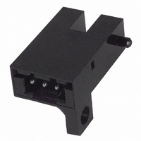
J ACCESSORIES (CONNECTOR WITH CABLE)
Refer to the following when using a non-dedicated connector.
Note: 1. For details, consult the manufacturer.
Precautions
J INSTALLATION CONNECTIONS
Do not connect the EE-SPX to an AC (100 VAC) power supply.
Doing so may cause ignition, burning, or other damage.
Do not use the EE-SPX at voltages exceeding the rated voltage
range. Doing so may cause the EE-SPX to be damaged or
burned.
Wire the EE-SPX correctly with the correct polarity. Failure to do
so may cause the EE-SPX to be damaged or burned.
Do not short-circuit the load (i.e., do not connect a power supply
directly to the Sensor) as shown below. Doing so may cause the
EE-SPX to be damaged or burned.
EE-1013
Sensor
Manufacturer
Housing
Contact
Applied power line
Sensor
5
pp
2. The applicable range for the applied power line is different from that specified by the manufacturer (AWG# 28 to 22).
3. When using a cable longer than 4 m, refer to Correct Design Setup in the Precautions section.
Brown
Brown
Blue
Blue
p
Black
Black
(0.39)
9.8
Load
Load
2.5 (0.10)
(0.22)
5.7
3
2
1
(0.31)
7.75
J.S.T. MFG. CO., LTD.
XHP-3
SXH-001T-P0.6
Cross section
AWG#
Insulator diameter
J.S.T. MFG. CO., LTD.
XHP-3
(0.79)
20
Vinyl insulated round cable (3.5 dia., three conductors)
(Conductor cross-section: 0.14 mm
Standard length: 1 m
J CORRECT DESIGN SETUP
Cable Extensions
Use a cable with a minimum wiring cross-section surface area of
0.15 mm
exceeds 4 m, connect a 10 µF capacitor within the 4 m mark, as
shown in the diagram. (Use a condenser with a withstand
pressure of at least twice the sensor power source voltage.)
(39.37)
1,000
Sensor
Brown
Blue
2
Black
and no greater than 4 m in length. If the wiring
(0.63±
16±
0.162 to 0.324 mm
25 to 22
1.2 to 1.9 mm
Load
Capacitor
10 µF min.
2
0.08
4 m max.
5 to 24 VDC
)
2
, insulator diameter: 1 mm)
(0.28±
Load
short-circuiting
7±
0 V
1
0.04
)
Terminal arrangement
2
Extension cable
1 Blue
2 Black
3 Brown Vcc
GND (0 V)
OUTPUT
Related parts for EE-SPX742
Image
Part Number
Description
Manufacturer
Datasheet
Request
R

Part Number:
Description:
PHOTO MICROSENSOR 0.5MM DARK ON
Manufacturer:
Omron
Datasheet:

Part Number:
Description:
OPTO SENSOR 5MM LT/DARKON PNP
Manufacturer:
Omron
Datasheet:

Part Number:
Description:
OPTO SENSOR 5MM LIGHTON NPN
Manufacturer:
Omron
Datasheet:

Part Number:
Description:
OPTO SENSOR 5MM LT/DARKON PNP
Manufacturer:
Omron
Datasheet:

Part Number:
Description:
OPTO SENSOR 5MM LT/DARKON NPN
Manufacturer:
Omron
Datasheet:

Part Number:
Description:
SENSOR OPTO 5MM LIGHT-ON TRANS
Manufacturer:
Omron
Datasheet:

Part Number:
Description:
OPTO SENSOR 5MM LT/DARKON PNP
Manufacturer:
Omron
Datasheet:

Part Number:
Description:
OPTO SENSOR 13MM SLOT LIGHT-ON
Manufacturer:
Omron
Datasheet:

Part Number:
Description:
SENSOR PHOTOMICRO 5-24VDC 2M
Manufacturer:
Omron
Datasheet:

Part Number:
Description:
OPTO SENSOR 8MM WIDE SLOT TYPE
Manufacturer:
Omron
Datasheet:


Part Number:
Description:
PHOTO MICROSENSOR
Manufacturer:
Omron
Datasheet:

Part Number:
Description:
PHOTO MICROSENSOR :
Manufacturer:
Omron
Datasheet:
Part Number:
Description:
PHOTO MICROSENSOR
Manufacturer:
Omron
Datasheet:

Part Number:
Description:
PHOTO MICROSENSOR
Manufacturer:
Omron
Datasheet: