QRD1114 Fairchild Optoelectronics Group, QRD1114 Datasheet - Page 2
QRD1114
Manufacturer Part Number
QRD1114
Description
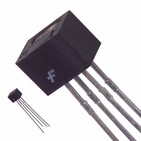
SENSR OPTO TRANS 1.27MM REFL PCB
Manufacturer
Fairchild Optoelectronics Group
Datasheet
1.QRD1114.pdf
(4 pages)
Specifications of QRD1114
Sensing Distance
0.050" (1.27mm)
Sensing Method
Reflective
Voltage - Collector Emitter Breakdown (max)
30V
Current - Dc Forward (if)
50mA
Output Type
Phototransistor
Response Time
10µs, 50µs
Mounting Type
Through Hole
Package / Case
PCB Mount
Operating Temperature
-40°C ~ 85°C
Lead Free Status / RoHS Status
Lead free / RoHS Compliant
Current - Collector (ic) (max)
-
Other names
QRD1114QT
QRD1114QT
QRD1114QT
Available stocks
Company
Part Number
Manufacturer
Quantity
Price
Company:

Part Number:
QRD1114
Manufacturer:
FSC
Quantity:
36 200
Company:
Part Number:
QRD1114
Manufacturer:
FAIRCHILD
Quantity:
3 200
Part Number:
QRD1114
Manufacturer:
FSC
Quantity:
20 000


©2005 Fairchild Semiconductor Corporation
QRD1113, QRD1114 Rev. 1.1.0
Absolute Maximum Ratings
Stresses exceeding the absolute maximum ratings may damage the device. The device may not function or be
operable above the recommended operating conditions and stressing the parts to these levels is not recommended.
In addition, extended exposure to stresses above the recommended operating conditions may affect device reliability.
The absolute maximum ratings are stress ratings only.
Electrical/Optical Characteristics
Notes:
1. Derate power dissipation linearly 1.33mW/°C above 25°C.
2. RMA flux is recommended.
3. Methanol or isopropyl alcohols are recommended as cleaning agents.
4. Soldering iron tip 1/16” (1.6 mm) minimum from housing.
5. As long as leads are not under any stress or spring tension.
6. D is the distance from the sensor face to the reflective surface.
7. Crosstalk (I
8. Measured using Eastman Kodak neutral white test card with 90% diffused reflecting as a reflecting surface.
EMITTER
SENSOR
INPUT (Emitter)
OUTPUT (Sensor)
COUPLED
Symbol Parameter
V
BV
BV
I
I
CE(SAT)
C(ON)
C(ON)
I
V
I
I
CX
PE
t
t
Symbol
CEO
ECO
R
D
r
f
F
T
T
T
V
V
T
SOL-F
SOL-I
OPR
V
P
P
STG
CEO
ECO
I
F
R
D
D
Forward Voltage
Reverse Leakage Current
Peak Emission Wavelength
Collector-Emitter Breakdown
Emitter-Collector Breakdown
Dark Current
QRD1113 Collector Current
QRD1114 Collector Current
Collector Emitter Saturation
Voltage
Cross Talk
Rise Time
Fall Time
CK
) is the collector current measured with the indicated current on the input diode and with no reflective surface.
Parameter
Operating Temperature
Storage Temperature
Lead Temperature (Solder Iron)
Lead Temperature (Solder Flow)
Continuous Forward Current
Reverse Voltage
Power Dissipation
Collector-Emitter Voltage
Emitter-Collector Voltage
Power Dissipation
(1)
(1)
(T
A
I
V
I
I
I
V
I
I
I
I
= 25°C unless otherwise specified)
F
F
C
E
F
F
F
F
V
R
CE
CE
= 20mA
= 20mA
= 20mA, V
= 20mA, V
= 40mA, I
= 20mA, V
= 0.1mA
= 1mA
= 5V
(T
= 10 V, I
= 5V, R
A
= 25°C)
(2,3)
(2,3)
Test Conditions
C
L
F
CE
CE
CE
= 100µA, D = .050"
= 100 , I
= 0mA
2
= 5V, D = .050"
= 5V, D = .050"
= 5V, E
E
C(ON)
= 0
(7)
= 5mA
(6,8)
(6,8)
(6,8)
0.300
Min.
260 for 10 sec
240 for 5 sec
30
-40 to +100
5
1
-40 to +85
Rating
100
100
50
30
5
Typ.
.200
940
10
50
Max.
100
100
1.7
0.4
10
www.fairchildsemi.com
Units
mW
mW
mA
°C
°C
°C
°C
V
V
V
Units
mA
mA
nm
µA
nA
µA
µs
µs
V
V
V
V
Related parts for QRD1114
Image
Part Number
Description
Manufacturer
Datasheet
Request
R

Part Number:
Description:
LED 7-SEG SGL CC RED RHDP .3"
Manufacturer:
Fairchild Optoelectronics Group
Datasheet:

Part Number:
Description:
LED IR EMITTING 940NM SIDELOOKER
Manufacturer:
Fairchild Optoelectronics Group
Datasheet:

Part Number:
Description:
LED IR EMITTING GAAS 940NM 3MM
Manufacturer:
Fairchild Optoelectronics Group
Datasheet:
Part Number:
Description:
LED IR EMITTING ALGAAS 880NM 3MM
Manufacturer:
Fairchild Optoelectronics Group
Datasheet:
Part Number:
Description:
LED IR EMITTING 940NM SMD 2MM
Manufacturer:
Fairchild Optoelectronics Group
Datasheet:
Part Number:
Description:
IC PHOTOTRANS IR 940NM BLK 1.9MM
Manufacturer:
Fairchild Optoelectronics Group
Datasheet:
Part Number:
Description:
LED IR GAAS SIDELOOK 940NM
Manufacturer:
Fairchild Optoelectronics Group
Datasheet:
Part Number:
Description:
LED IR EMITTING 940NM 2MM SMD
Manufacturer:
Fairchild Optoelectronics Group
Datasheet:
Part Number:
Description:
IC PHOTOTRANS IR 940NM 1.9MM GW
Manufacturer:
Fairchild Optoelectronics Group
Datasheet:
Part Number:
Description:
LED IR EMITTING 880NM 2-PLCC
Manufacturer:
Fairchild Optoelectronics Group
Datasheet:
Part Number:
Description:
LED 7-SEG SGL CC RED RHDP .3"
Manufacturer:
Fairchild Optoelectronics Group
Datasheet:

Part Number:
Description:
DIODE EMITTING GAAS IRED TO-46
Manufacturer:
Fairchild Optoelectronics Group
Datasheet:
Part Number:
Description:
DIODE EMITTING GAAS IRED TO-46
Manufacturer:
Fairchild Optoelectronics Group
Datasheet:

Part Number:
Description:
LED SS BIPO RED/GRN DIFF PCB 5MM
Manufacturer:
Fairchild Optoelectronics Group
Datasheet:

Part Number:
Description:
LED SS HI EFF GREEN DIFF 3MM
Manufacturer:
Fairchild Optoelectronics Group
Datasheet: