EE-SB5 Omron, EE-SB5 Datasheet
EE-SB5
Manufacturer Part Number
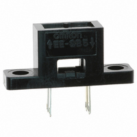
EE-SB5
Description
SENSR OPTO TRANS 5MM REFL SOLDER
Manufacturer
Omron
Type
Infraredr
Specifications of EE-SB5
Sensing Distance
0.197" (5mm)
Sensing Method
Reflective
Voltage - Collector Emitter Breakdown (max)
30V
Current - Collector (ic) (max)
20mA
Current - Dc Forward (if)
50mA
Output Type
Phototransistor
Response Time
30µs, 30µs
Mounting Type
Solder
Package / Case
PCB Mount
Operating Temperature
-25°C ~ 80°C
Output Configuration
Phototransistor
No. Of Channels
1
Optocoupler Output Type
Phototransistor
Input Current
30mA
Output Voltage
30V
Opto Case Style
Through Hole
No. Of Pins
4
Operating Temperature Range
-25°C To +80°C
Current, Switching
20 mA
Function
Proximity
Indicator
LED
Light Source
Infrared LED
Material, Body
ABS
Material, Lens
Plastic
Output
NPN
Primary Type
Photoelectric
Sensing Mode
Reflective
Standards
UL Listed
Technology
Photoelectric
Temperature, Operating
-25 to +85 °C
Termination
Solder
Voltage, Supply
1.5 V
Voltage, Switching
30 V
Wide Operating Range
5 to 24 VDC
Input Current Max
30mA
Rohs Compliant
Yes
Lead Free Status / RoHS Status
Lead free / RoHS Compliant
Lead Free Status / RoHS Status
Lead free / RoHS Compliant, Lead free / RoHS Compliant
Other names
EESB5
OR500
OR500
Available stocks
Company
Part Number
Manufacturer
Quantity
Price
Company:

Part Number:
EE-SB5
Manufacturer:
Omron Electronics
Quantity:
135
Company:
Part Number:
EE-SB5-B
Manufacturer:
omRon
Quantity:
10
Company:
Part Number:
EE-SB5MC
Manufacturer:
JRC
Quantity:
1 500
Note: All units are in millimeters unless otherwise indicated.
Note: The letter “d” indicates the distance between the top surface of the sensor and the sensing object.
216
EE-SB5(-B)
11.5±0.2
Emitter
Detector
Rising time
Falling time
A
K
Terminal No.
A
K
C
E
Dimensions
Electrical and Optical Characteristics (Ta = 25°C)
9±0.2
Internal Circuit
7.62±0.3
Forward voltage
Reverse current
Peak emission wavelength
Light current
Dark current
Leakage current
Collector–Emitter saturated
voltage
Peak spectral sensitivity
wavelength
Name
Anode
Cathode
Collector
Emitter
Item
C
E
Four, 0.25
Two, 3.2 dia. holes
Unless otherwise specified, the
tolerances are as shown below.
Dimensions
3 mm max.
3 t mm v 6
6 t mm v 10
10 t mm v 18
18 t mm v 30
2.54±0.2
Optical axis
EE-SB5
V
I
λ
I
I
I
V
λ
tr
tf
R
L
D
LEAK
P
P
F
CE
Symbol
Tolerance
±0.3
±0.375
±0.45
±0.55
±0.65
Four, 0.5
(sat)
Optical axis
2.54±0.2
EE-SB5-B
1.2 V typ., 1.5 V max.
0.01 µA typ., 10 µA max.
940 nm typ.
200 µA min., 2,000 µA max.
2 nA typ., 200 nA max.
2 µA max.
---
850 nm typ.
30 µs typ.
30 µs typ.
•
•
•
•
•
Note: 1. Refer to the temperature rating chart if the ambient
Emitter
Detector
Ambient
temperature
Soldering temperature
Features
Dust-tight construction.
With a visible-light intercepting filter which allows objects to
be sensed without being greatly influenced by the light
radiated from fluorescent lamps.
Mounted with M3 screws.
Model with soldering terminals (EE-SB5).
Model with PCB terminals (EE-SB5-B).
Absolute Maximum Ratings
(Ta = 25°C)
Value
2. The pulse width is 10 µs maximum with a frequency
3. Complete soldering within 10 seconds.
Photomicrosensor
temperature exceeds 25°C.
of 100 Hz.
Item
Forward current
Pulse forward
current
Reverse voltage
Collector–Emitter
voltage
Emitter–Collector
voltage
Collector current I
Collector
dissipation
Operating
Storage
I
V
I
I
White paper with a reflection ratio
of 90%, d = 5 mm (see note)
V
I
reflection
---
V
V
V
F
F
F
F
R
CE
CE
CC
CC
= 30 mA
= 20 mA
= 20 mA, V
= 20 mA, V
= 4 V
= 10 V, 0 x
= 10 V
= 5 V, R
= 5 V, R
I
I
V
V
V
P
Topr
Tstg
Tsol
Symbol
F
FP
C
Condition
R
CEO
ECO
C
L
L
(Reflective)
CE
CE
= 1 kΩ, I
= 1 kΩ, I
= 10 V
= 10 V with no
50 mA
(see note 1)
1 A
(see note 2)
4 V
30 V
---
20 mA
100 mW
(see note 1)
–25°C to
80°C
–30°C to
80°C
260°C
(see note 3)
L
L
= 1 mA
= 1 mA
Rated
value
Related parts for EE-SB5
Image
Part Number
Description
Manufacturer
Datasheet
Request
R

Part Number:
Description:
OPTO SENSOR SLOT TYPE 5MM
Manufacturer:
Omron
Datasheet:

Part Number:
Description:
Optical Sensor (Switch) Transmissive / Slotted Interrupter
Manufacturer:
Omron
Datasheet:

Part Number:
Description:
PHOTOMICROSENSOR, TRANSISTOR
Manufacturer:
Omron
Datasheet:

Part Number:
Description:
SENSR OPTO SLOT 3.4MM TRANS THRU
Manufacturer:
Omron
Datasheet:

Part Number:
Description:
OPTO SENSOR SLOT TYPE 3MM
Manufacturer:
Omron
Datasheet:

Part Number:
Description:
SENSOR OPTO TRANS 4.4MM REFL PCB
Manufacturer:
Omron
Datasheet:

Part Number:
Description:
OPTO SENSOR REFLECT TYPE 4MM
Manufacturer:
Omron
Datasheet:

Part Number:
Description:
PHOTO MICROSENSOR :
Manufacturer:
Omron
Datasheet:

Part Number:
Description:
SENSOR OPTO TRANS 3.5MM REFL PCB
Manufacturer:
Omron
Datasheet:

Part Number:
Description:
PHOTO MICROSENSOR
Manufacturer:
Omron
Datasheet:


Part Number:
Description:
PHOTO MICROSENSOR
Manufacturer:
Omron
Datasheet:
Part Number:
Description:
PHOTO MICROSENSOR :
Manufacturer:
Omron
Datasheet:

Part Number:
Description:
PHOTO MICROSENSOR
Manufacturer:
Omron
Datasheet:

Part Number:
Description:
PHOTO MICROSENSOR
Manufacturer:
Omron
Datasheet: