HS16-1 NKK Switches, HS16-1 Datasheet - Page 2
HS16-1
Manufacturer Part Number
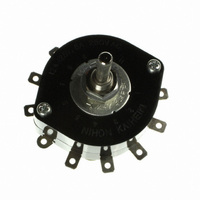
HS16-1
Description
SWITCH ROTARY NON-SHORTING 1POLE
Manufacturer
NKK Switches
Series
HSr
Datasheet
1.AT432.pdf
(5 pages)
Specifications of HS16-1
Number Of Positions
2 ~ 11
Number Of Decks
1
Number Of Poles Per Deck
1
Circuit Per Deck
SP11T
Contact Rating @ Voltage
12A @ 125VAC
Actuator Type
Knurled (6mm Dia)
Mounting Type
Panel Mount
Termination Style
Solder Lug
Orientation
Vertical
Angle Of Throw
30°
Lead Free Status / RoHS Status
Lead free / RoHS Compliant
Other names
HS16-1-RO
HS16-1-RO
HS16-1-RO
Available stocks
Company
Part Number
Manufacturer
Quantity
Price

Part Number:
HS16-102
Manufacturer:
THCOM
Quantity:
20 000


Standard Size Rotaries
Nonshorting
Switch is viewed from shaft end and shown in position 1. Terminal numbers are not on switch. Standard Hardware shown on last page of this section.
*
Switch is viewed from shaft end and shown in position 1. Terminal numbers are not on switch. Standard Hardware shown on last page of this section.
*
(4.8) Typ
.189
Maximum Effective Panel Thickness
HS13X
HS13Y
HS13Z
(65.0)
2.559
Round
Shaft
Wire harness & cable assemblies offered only in Americas.
HS16-1
HS16-2
HS16-3
HS16-4
HS16-5
HS16-6
Wire harness & cable assemblies offered only in Americas.
Keyway
Knurled Shaft
Without Locking Ring
With Locking Ring
(3.0) Dia
.118
(34.0) Dia
1.339
.189” (4.8mm)
.228” (5.8mm)
(10.5) Dia
.413
.354
(9.0)
HS13X-D
HS13Z-D
HS13Y-D
D-flat
Shaft
HS16-1S
HS16-2S
HS16-3S
HS16-4S
HS16-5S
HS16-6S
Shorting
(55.0)
2.165
Number of
.236
(6.0) Dia
Positions
M10 P0.75
.059
(10.3) Dia
.406
(1.5)
12 AMP/SHORTING & NONSHORTING/30° INDEXING
6 AMP SINGLE POLE/NONSHORTING/45° INDEXING
Nonshorting
2
3
4
HS16-1N
HS16-2N
HS16-3N
HS16-4N
HS16-5N
HS16-6N
(9.5)
.374
(10.0)
.394
(4.4)
.173
D-flat Shaft
(10.0)
.394
Stopper
Settings
(40.0)
1.575
Fixed
Fixed
Fixed
.236
• On each deck of multipole devices common and load terminals
• Switch is viewed from the shaft end and shown in position 1.
• Terminal numbers are on the switch bottom. Stopper positions
• Standard Hardware shown on last page of this section.
(6.0) Dia
(0.3)
.012
(16.0)
.630
are in the same positions as shown in the schematic above.
are molded on the top of the switch.
HS16-1SN
HS16-2SN
HS16-3SN
HS16-4SN
HS16-5SN
HS16-6SN
Shorting
M10 P0.75
Keyway
.028
(0.7) Typ
(10.0)
.394
(15.0)
1 COM, 2 LOAD
1 COM, 3 LOAD
1 COM, 4 LOAD
.224
.591
(5.7) Typ
Number of
Terminals
(14.0)
.551
Pole
1P
2P
3P
4P
5P
6P
COM
(24.5)
*
.965
4
Number of
(34.5)
1.358
Positions
(2.6) Dia Typ
.102
2-11
2-11
2-11
2-11
2-11
2-11
1, 2, 3, & 4
3
www.nkk.com
(44.5)
1.752
Terminals
1, 2, & 3
2.933
1
(74.5)
1 & 2
Load
2
(54.5)
2.146
2, 3, 4 . . . 11
2, 3, 4 . . . 11
2, 3, 4 . . . 11
2, 3, 4 . . . 11
2, 3, 4 . . . 11
2, 3, 4 . . . 11
(64.5)
2.539
Stopper
Settings
Maximum Effective Panel Thickness
HS13X
C 1
1
Without Locking Ring
2
With Locking Ring
(3.0) Dia
.118
.150” (3.8mm)
.189” (4.8mm)
(10.5) Dia
C L of Keyway
.413
(9.0)
.354
(0.84) Typ
.033
.276
(7.0) Max
1 COM, 11 LOAD
2 COM, 22 LOAD
3 COM, 33 LOAD
4 COM, 44 LOAD
5 COM, 55 LOAD
6 COM, 66 LOAD
Terminals
Number of
(2.6) Dia Typ
.102
HS16-2N
HS13Y
Schematics
*
.059
C 1
(10.3) Dia
.406
(1.5)
1
2
.374
(9.5)
C L of Keyway
Series HS
3
10
9
11
8
Schematic
C 1
7
(6.24) Typ
.246
HS13Z
HS13X
6
1
C 1
1
2
5
2
C L of Keyway
4
3
(8.0) Typ
.315
C L of Keyway
3
G47
4
G
Related parts for HS16-1
Image
Part Number
Description
Manufacturer
Datasheet
Request
R

Part Number:
Description:
Rotary Switches 12 AMP 3P 2-11 POS
Manufacturer:
NKK Switches
Datasheet:
Part Number:
Description:
Rotary Switches 12AMP 1P 2-11 POS
Manufacturer:
NKK Switches
Datasheet:
Part Number:
Description:
Rotary Switches 5P 11 POS KNURLED SHAFT SHORTING 12A
Manufacturer:
NKK Switches
Datasheet:

Part Number:
Description:
Rotary Switches 12 AMP 4P 2-11 POS
Manufacturer:
NKK Switches
Datasheet:
Part Number:
Description:
Rotary Switches 12 AMP 6P 2-11 POS
Manufacturer:
NKK Switches
Datasheet:

Part Number:
Description:
Rotary Switches 12 AMP 5P 2-11 POS
Manufacturer:
NKK Switches
Datasheet:
Part Number:
Description:
Rotary Switches SP 11 POS KNURLED SHAFT 12A
Manufacturer:
NKK Switches
Datasheet:
Part Number:
Description:
Rotary Switches 12A 2POLE SHORTING
Manufacturer:
NKK Switches
Datasheet:
Part Number:
Description:
Rotary Switches 12A 6 POLE SHORTING
Manufacturer:
NKK Switches
Datasheet:
Part Number:
Description:
Rotary Switches 6P 11 POS KNURLED SHAFT 12A SOLDER LUG
Manufacturer:
NKK Switches
Datasheet:

Part Number:
Description:
ON-OFF PLATE - SERIES -EMP
Manufacturer:
NKK Switches
Datasheet:

Part Number:
Description:
WRENCH SOCKET FOR KB SERIES PB
Manufacturer:
NKK Switches
Datasheet:

Part Number:
Description:
SWITCH TOGGLE DPST 25A SLDR 5PCS
Manufacturer:
NKK Switches
Datasheet:

Part Number:
Description:
SWITCH TOGGLE DPDT 15A SLDR 5PC
Manufacturer:
NKK Switches
Datasheet:

Part Number:
Description:
SWITCH TOGGLE 4PST 25A SLDR 5PCS
Manufacturer:
NKK Switches
Datasheet: