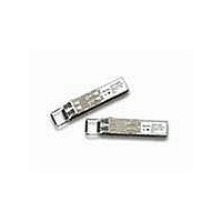
AFBR-57R6AEZ Avago Technologies US Inc., AFBR-57R6AEZ Datasheet

AFBR-57R6AEZ
Specifications of AFBR-57R6AEZ
Available stocks
Related parts for AFBR-57R6AEZ
AFBR-57R6AEZ Summary of contents
Page 1
... ANSI Fibre Channel FC-PI, FC-PI-2 and com- pliant with IEEE 802.3 for gigabit applications. The part is electrically interoperable with SFP conformant devices. The AFBR-57R6AEZ is a “Quad Rate” 850 nm SFP which ensures compliance to 4G/2G/1G Fibre Channel and 1G Ethernet specifications. Using the product’s Rate_Select input, the user sets the desired SFP compliance point ...
Page 2
... Installation The AFBR-57R6AEZ can be installed in any SFF-8074i compliant Small Form Pluggable (SFP) port regardless of host equipment operating status. The AFBR-57R6AEZ is hot-pluggable, allowing the module to be installed while the host system is operating and on-line. Upon insertion, the transceiver housing makes initial contact with the host board SFP cage, mitigating potential damage due to Electro-Static Discharge (ESD) ...
Page 3
... A2, byte 110, bit 2). Eye Safety Circuit The AFBR-57R6AEZ provides Class 1 (single fault tolerant) eye safety by design and has been tested for compliance with the requirements listed in Table 1. The eye safety ...
Page 4
... AFBR-57R6AEZ. All mechanical adjust- ments are made at the factory prior to shipment. Tampering with, modifying, misusing or improperly handling the AFBR-57R6AEZ will void the product warranty. It may also result in improper operation and possibly overstress the la- ser source. Performance degrada tion or device failure may result ...
Page 5
... TUV TYPE Rheinland APPROVED Product Safety Component Recognition RoHS Compliance 5 Flammability The AFBR-57R6AEZ optical transceiver is made of metal and high strength, heat resistant, chemical resistant and UL 94V-0 flame retardant plastic. Test Method MIL-STD-883C Method 3015.4 Variation of IEC 61000-4-2 GR1089 Variation of IEC 801-2 ...
Page 6
Tx_DISABLE Tx_FAULT SERDES IC PROTOCOL IC LOSS OF SIGNAL RATE SELECT 4 MODULE DETECT SCL SDA Figure 2. Typical application configuration 0 0 SFP MODULE HOST ...
Page 7
Table 2. Pin Description Pin Name Function/Description 1 VeeT Transmitter Ground 2 TX_FAULT Transmitter Fault Indication – High indicates a fault condition 3 TX_DISABLE Transmitter Disable – Module electrical input disables on high or open 4 MOD-DEF2 Module Definition 2 ...
Page 8
Table 3. Absolute Maximum Ratings Parameter Storage Temperature Case Operating Temperature Relative Humidity Supply Voltage Low Speed Input Voltage Notes: 1. Absolute Maximum Ratings are those values beyond which damage to the device may occur if these limits are exceeded ...
Page 9
Table 6. Transmitter and Receiver Electrical Characteristics (T = -10°C to 85°C, VccT, VccR = 3.3 V ± 10%) C Parameter High Speed Data Input: Transmitter Differential Input Voltage (TD +/-) High Speed Data Output: Receiver Differential Output Voltage (RD ...
Page 10
Table 7. Transmitter Optical Characteristics (T = -10°C to 85°C, VccT, VccR = 3.3V ±10%) C Parameter Modulated Optical Output Power (OMA) (Peak-to-Peak) 4.25 Gb/s Modulated Optical Output Power (OMA) (Peak-to-Peak) 2.125 Gb/s Modulated Optical Output Power (OMA) (Peak-to-Peak) 1.0625 ...
Page 11
Table 8. Receiver Optical Characteristics (T = -10°C to 85°C, VccT, VccR = 3.3 V ±10%) C Parameter Input Optical Power [Overdrive] Input Optical Modulation Amplitude (Peak-to-Peak) 4.25 Gb/s [Sensitivity] Input Optical Modulation Amplitude (Peak-to-Peak) 2.125 Gb/s [Sensitivity] Input Optical ...
Page 12
Table 9. Transceiver SOFT DIAGNOSTIC Timing Characteristics (T = -10°C to 85°C, VccT, VccR = 3.3 V ± 10%) C Parameter Hardware TX_DISABLE Assert Time Hardware TX_DISABLE Negate Time Time to initialize, including reset of TX_FAULT Hardware TX_FAULT Assert Time ...
Page 13
Table 10. Transceiver Digital Diagnostic Monitor (Real Time Sense) Characteristics (T = -10°C to 85°C, VccT, VccR = 3.3 V ± 10%) C Parameter Transceiver Internal Temperature Accuracy Transceiver Internal Supply Voltage Accuracy Transmitter Laser DC Bias Current Accuracy Transmitted ...
Page 14
... Addresses 63 and 95 are checksums calculated (per SFF-8472 and SFF-8074) and stored prior to product shipment. 7. Addresses 68-83 specify the AFBR-57R6AEZ ASCII serial number and will vary on a per unit basis. 8. Addresses 84-91 specify the AFBR-57R6AEZ ASCII date code and will vary on a per date code basis. 14 ...
Page 15
... Transmitted average optical power (Tx Pwr) is decoded bit unsigned integer in increments of 0.1 μW. 5. Received average optical power (Rx Pwr) is decoded bit unsigned integer in increments of 0.1 μW. 6. Bytes 56-94 are not intended for use with AFBR-57R6AEZ, but have been set to default values per SFF-8472. 7. Byte checksum calculated (per SFF-8472) and stored prior to product shipment. ...
Page 16
... Bit 6 is logic OR’d with the SFP TX_DISABLE input pin 3 ... either asserted will disable the SFP transmitter. 3. AFBR-57R6AEZ is optimized for 4.25 G, 2.125 Gb/s, and 1.0625 Gb/s performance when the Rate_Select (pin 7) is high. The AFBR-57R6AEZ is optimized for 2.125 Gb/s and 1.0625 Gb/s Fibre Channel and 1.25 Gb/s Ethernet performance when the Rate_Select (pin 7) is low. Bit 3 is logic OR’ ...
Page 17
... DUST CAP AND BAIL DELATCH 6.25 – 0. Figure 5. Module drawing 17 55.3 – 0.2 Avago 13.6 PPOG-4402-Din2 1.91 1.39 UNCOMPRESSED 12.4 – 0.2 0.55 UNCOMPRESSED 13.6 14.9 UNCOMPRESSED AFBR-57R6AEZ 850nm LASER PROD 21CRF(J) CLASS1 CHINA 0445 13.4 – 0.1 SN: A30445CD1C 8.5 – 0.1 ...
Page 18
X Y 10x 16.25 MIN. PITCH B PCB EDGE 5.68 8.58 11.08 16.25 14.25 REF. 2.0 11x 3 5 3.2 0.9 20 PIN 1 10.93 9.6 0.8 TYP 1.55 0.05 0 ...
Page 19
MAX. 11.73 REF 9.8 MAX. PCB Figure 7. SFP Assembly drawing Customer Manufacturing Processes This module is pluggable and is not designed for aqueous wash, IR reflow, or wave soldering processes. For product ...


