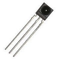
TSOP4136 Vishay, TSOP4136 Datasheet - Page 2

TSOP4136
Manufacturer Part Number
TSOP4136
Description
Infrared Receivers 4.5-5.5V 36kHz
Manufacturer
Vishay
Datasheet
1.TSOP4138.pdf
(7 pages)
Specifications of TSOP4136
Carrier Frequency
36 KHz
Supply Current
0.85 mA
Beam Angle
45 deg
Data Transmission Rate
4000 bits/s
Mounting Style
Through Hole
Transmission Distance
45 m
Viewing Angle
45 deg
Output Current
5 mA
Operating Voltage
2.7 V to 5.5 V
Power Dissipation
10 mW
Maximum Operating Temperature
+ 85 C
Minimum Operating Temperature
- 25 C
Transmission Range
45m
Directivity
45°
Supply Voltage Range
2.7V To 5.5V
Opto Case Style
Through Hole
Operating Temperature Range
-25°C To +85°C
Operating Supply Voltage (typ)
3.3/5V
Operating Supply Voltage (min)
2.7V
Operating Supply Voltage (max)
5.5V
Mounting
Through Hole
Pin Count
3
Operating Temperature Classification
Commercial
Lead Free Status / RoHS Status
Lead free / RoHS Compliant
Lead Free Status / RoHS Status
Lead free / RoHS Compliant, Lead free / RoHS Compliant
Available stocks
Company
Part Number
Manufacturer
Quantity
Price
Company:
Part Number:
TSOP4136
Manufacturer:
VISHAY
Quantity:
2 000
Company:
Part Number:
TSOP4136/TSOP4140
Manufacturer:
NEC
Quantity:
10 000
Company:
Part Number:
TSOP4136LL1
Manufacturer:
LITON
Quantity:
9 530
Company:
Part Number:
TSOP4136SS1BS12
Manufacturer:
VISHAY
Quantity:
2 025
Company:
Part Number:
TSOP4136ST1
Manufacturer:
VISHAY
Quantity:
10 907
TSOP21.., TSOP23.., TSOP41.., TSOP43..
Vishay Semiconductors
Note
• Stresses beyond those listed under “Absolute Maximum Ratings” may cause permanent damage to the device. This is a stress rating only
TYPICAL CHARACTERISTICS (T
www.vishay.com
2
ABSOLUTE MAXIMUM RATINGS
PARAMETER
Supply voltage
Supply current
Output voltage
Voltage at output to supply
Output current
Junction temperature
Storage temperature range
Operating temperature range
Power consumption
Soldering temperature
ELECTRICAL AND OPTICAL CHARACTERISTICS (T
PARAMETER
Supply current
Supply voltage
Transmission distance
Output voltage low
Minimum irradiance
Maximum irradiance
Directivity
and functional operation of the device at these or any other conditions beyond those indicated in the operational sections of this specification
is not implied. Exposure to absolute maximum rating conditions for extended periods may affect the device reliability.
V
V
V
O
OH
OL
E
e
Optical Test Signal
(IR diode TSAL6200, I
Output Signal
t
d
1)
t
pi
1)
2)
*)
3/f
t
pi
*) t
Fig. 1 - Output Active Low
0
- 4/f
pi
< t
≥ 6/f 0 is recommended for optimal function
d
0
< 9/f
< t
t
po
po
2)
F
T
0
< t
= 0.4 A, N = 6 pulses, f = f
pi
+ 6/f
0
I
OSL
E
Angle of half transmission
t 10 s, 1 mm from case
v
t
t
pi
pi
= 0.5 mA, E
= 0, test signal see fig. 1,
Pulse width tolerance:
IR diode TSAL6200,
test signal see fig. 1
test signal see fig. 1
test signal see fig. 1
E
TEST CONDITION
TEST CONDITION
- 5/f
- 5/f
amb
v
IR Receiver Modules for Remote
E
= 40 klx, sunlight
T
v
I
F
o
o
amb
= 0, V
= 25 °C, unless otherwise specified)
distance
< t
< t
= 400 mA
t
14337
0
po
po
85 °C
t
, t = 10 ms)
e
S
< t
< t
= 0.7 mW/m
= 5 V
Control Systems
pi
pi
+ 6/f
+ 6/f
o
o
,
,
2
,
amb
SYMBOL
E
E
V
e max.
e min.
I
I
V
OSL
SD
SH
d
1/2
SYMBOL
= 25 °C, unless otherwise specified)
S
V
S
T
T
P
T
Fig. 2 - Pulse Length and Sensitivity in Dark Ambient
V
V
I
amb
I
T
- V
stg
21391_1
S
O
tot
sd
O
S
j
0.35
0.30
0.25
0.20
0.15
0.10
0.05
O
0
0.1
MIN.
0.65
2.7
30
1
- 0.3 to (V
Optical Test Signal, Fig.1
E
e
- 25 to + 85
- 25 to + 85
- 0.3 to + 6
- 0.3 to 5.5
- Irradiance (mW/m²)
10
VALUE
λ = 950 nm,
TYP.
± 45
0.85
0.95
0.17
100
260
10
45
5
5
S
10
+ 0.3)
2
Output Pulse Width
Input Burst Length
10
Document Number: 82135
3
MAX.
1.05
0.35
100
5.5
10
Rev. 2.8, 04-Feb-11
4
10
UNIT
mW
mA
mA
°C
°C
°C
°C
5
V
V
V
mW/m
W/m
UNIT
deg
mA
mA
mV
m
V
2
2


