E3S-AR86 Omron, E3S-AR86 Datasheet - Page 11
E3S-AR86
Manufacturer Part Number
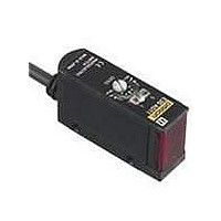
E3S-AR86
Description
Industrial Photoelectric Sensors PNP POLAR RETROREFL
Manufacturer
Omron
Type
Photoelectric Sensorr
Series
E3S-Ar
Specifications of E3S-AR86
Features
Control the laser with digital fiber amplifier
Height
22.3 mm
Length
40 mm
Maximum Operating Temperature
+ 55 C
Minimum Operating Temperature
- 25 C
Operating Supply Voltage
10 V to 30 V
Width
12.4 mm
Sensing Distance
2 m
Output Configuration
PNP
Output Current
100mA
Sensor Output
PNP
Supply Voltage Range Dc
10V To 30V
Sensing Range Max
2m
Sensor Housing
Rectangular
Switch Terminals
Connector
Sensor Input
Optical
Sensing Method
Retroreflective
Sensing Object
Mirror
Sensing Light
Red
Mounting Type
Chassis Mount
Current - Supply
30mA
Voltage - Supply
10 V ~ 30 V
Package / Case
Module, Connector
Sensing Mode
Polarized Retroreflective
Rohs Compliant
Yes
Lead Free Status / RoHS Status
Lead free / RoHS Compliant
Lead Free Status / RoHS Status
Lead free / RoHS Compliant, Lead free / RoHS Compliant
Available stocks
Company
Part Number
Manufacturer
Quantity
Price
Company:

Part Number:
E3S-AR86
Manufacturer:
OMRON
Quantity:
298


E39-E6 Polarized Mutual Interference Prevention Filters
for Through-beam Sensors
(Accessory, order separately)
Operating Mode Selection
As shown in the following illustration, the E3S-A has an
operating mode selector on the panel where the Receiver
connector is located.
With this operating mode selector, the E3S-A is in either Dark-
ON or Light-ON mode.
The Emitter of the Through-beam Sensor with the self-
diagnostic feature incorporates a turbo switch. When this
switch is ON, the intensity of the red LED light source can be
increased to make a brighter spot.
(ON when light is OFF)
• A set of 4 Filters are sold together for two Through-beam
• For mounting, refer to the figure of the Through-beam Slits.
• The arrow printed on the cover indicates the direction of
Sensors (for 2 each for Emitters and Receivers). Order one
for every two sets of Photoelectric Sensors.
polarization. By attaching the Filters opposite to each other
in polarization to the Emitters and the Receivers in rows,
mutual interference can be prevented (in any case, the
Filter attached to an Emitter and to the corresponding
Receiver must be the same in direction of polarization or the
Photoelectric Sensor will not function).
Timer
Receiver
Operating mode switch (black)
and
Dark ON
Turbo
Y = 0
D
The default operating mode is shown in the
following table.
Diffuse-reflective Sensors
Retro-reflective Sensors
Through-beam Sensors
http://www.ia.omron.com/
Switch
L
Emitter
Note: The arrows on the Filters can be attached in
Sensing method
Up to two units
can be attached.
Light ON
(ON when light is ON)
either direction when two Sensors are
mounted next to each other. The Filter
attached to an Emitter and to the
corresponding Receiver must be the same
in direction of polarization or the Sensor will
not function.
Default switch
Light-ON
Dark-ON
setting
The turbo function is effective with the turbo switch pressed,
and the function is reset automatically when released.
With the turbo function switched ON, the light spot is visible
even at a distance of 200 mm, making it easy to check the
sensing position and the angle of the optical axis.
Precautions
(1)Do not keep the turbo switch pressed for longer than 3
(2)Pressing the switch may change the timer delay settings.
(3)To press the switch, use a force of 9.8 N max.
Using the E39-R5 Optical Axis Reflector for Through-
beam Sensors
(Accessory, order Separately)
Use this attachment when the set distance is long and
adjustment is mechanically difficult with a sensing object.
• Attach the Reflector to the Receiver.
• Look at the Reflector from right behind the Emitter. The
• When the Reflector is removed, the light beam strikes the
Turbo
Reflector should be bright with red light when the optical
beam strikes the Reflector. If the Emitter has a turbo
function, the Reflector looks brighter with the function
switched ON.
Receiver.
minutes. (It will not break even if it is pressed for an
extended period.)
Set the timer after using the turbo function to check the
optical axis.
(c)Copyright OMRON Corporation 2008 All Rights Reserved.
Function (
The OFF-delay timer adjuster is
used as a turbo switch (black).
Eye
Sensitivity adjuster
E3S-AT@@
Emitter
Turbo
The intensity of the
red spot will be
increased, making
visual confirmation
much easier.
Switch)
E39-R5
Optical Axis Confirmation Reflector
E3S-AT@@
Receiver
PUSH
E3S-A
11
Related parts for E3S-AR86
Image
Part Number
Description
Manufacturer
Datasheet
Request
R

Part Number:
Description:
E3S-AT66 RECEIVER
Manufacturer:
Omron
Datasheet:

Part Number:
Description:
E3S-AT61 RECEIVER
Manufacturer:
Omron
Datasheet:
Part Number:
Description:
E3S-AT66 Emitter
Manufacturer:
Omron
Datasheet:
Part Number:
Description:
EMITTER ONLY FOR E3S-AT16
Manufacturer:
Omron
Datasheet:
Part Number:
Description:
RECEIVER ONLY FOR E3S-AT16
Manufacturer:
Omron
Datasheet:
Part Number:
Description:
RECEIVER ONLY FOR E3S-AT11
Manufacturer:
Omron
Datasheet:
Part Number:
Description:
EMITTER ONLY FOR E3S-AT11
Manufacturer:
Omron
Datasheet:

Part Number:
Description:
OPTO SENSOR XMITTER/RCVR HORZ
Manufacturer:
Omron
Datasheet:
Part Number:
Description:
PHOTOELECTRIC
Manufacturer:
Omron
Datasheet:
Part Number:
Description:
PHOTOELECTRIC
Manufacturer:
Omron
Datasheet:

Part Number:
Description:
G6S-2GLow Signal Relay
Manufacturer:
Omron Corporation
Datasheet:
Part Number:
Description:
Compact, Low-cost, SSR Switching 5 to 20 A
Manufacturer:
Omron Corporation
Datasheet:
Part Number:
Description:
Manufacturer:
Omron Corporation
Datasheet: