OPB840L51 Optek, OPB840L51 Datasheet - Page 4
OPB840L51
Manufacturer Part Number
OPB840L51
Description
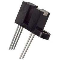
Photointerruptors Slotted Opt Switch
Manufacturer
Optek
Datasheet
1.OPB840L11.pdf
(8 pages)
Specifications of OPB840L51
Maximum Operating Temperature
+ 85 C
Minimum Operating Temperature
- 40 C
Wavelength
890 nm
Sensing Method
Slotted Optical Switch
Output Collector Emitter Voltage (detector)
30 V
Maximum Reverse Voltage (emitter)
2 V
Maximum Collector Current (detector)
30 mA
Slot Width
3.18 mm
Aperture Width
0.25 mm
Output Device
Phototransistor
Power Dissipation
100 mW
Lead Free Status / RoHS Status
Lead free / RoHS Compliant
Available stocks
Company
Part Number
Manufacturer
Quantity
Price
Company:

Part Number:
OPB840L51
Manufacturer:
Optek
Quantity:
466


Slotted Optical Switch
OPB830 and OPB840 Series (L & W)
Absolute Maximum Ratings
Input Diode
Output Phototransistor
Electrical Characteristics
Input Diode LED (See OP240 for additional information—for reference only)
Output Transistor (See OP550 for additional information—for reference only)
Issue A.2
Page 4 of 8
SYMBOL
V
V
(BR)CEO
(BR)ECO
Notes:
I
V
CEO
I
Storage and Operating Temperature
Lead Soldering Temperature [1/16 inch (1.6mm) from the case for 5 sec. with soldering iron]
Forward DC Current
Peak Forward Current (1 µs pulse width, 300 pps)
Reverse DC Voltage
Power Dissipation
Collector-Emitter Voltage
Emitter-Collector Voltage
Collector DC Current
Power Dissipation
R
(1) Derate linearly 1.67 mW/° C above 25° C for L Series.
(2) RMA flux is recommended. Duration can be extended to 10 seconds maximum when flow soldering.
(3) Methanol or isopropanol are recommended as cleaning agents. Plastic housing is soluble in chlorinated hydrocarbons and
(4) The W Series includes wire terminations of 24” (610 mm) 7-strand, 26 AWG UL insulated wire on each terminal. Each device
(5) All parameters tested using pulse technique.
F
L Series
W Series
ketones.
incorporates a wire strain relief at the housing surface. The insulation functions and colors are: anode (red), cathode (black),
phototransistor collector (white) and phototransistor emitter (green).
10/08
Forward Voltage
Reverse Current
Collector-Emitter Breakdown Voltage
Emitter-Collector Breakdown Voltage
Collector-Emitter Dark Current
OPTEK reserves the right to make changes at any time in order to improve design and to supply the best product possible.
(1)
(1)
(1)
(1)
PARAMETER
(T
A
(T
= 25°C unless otherwise noted)
Phone: (972) 323-2200 or (800) 341-4747
A
=25°C unless otherwise noted)
MIN
30
5
-
-
-
TYP
-
-
-
-
-
MAX
100
100
1.7
-
-
OPTEK Technology Inc. — 1645 Wallace Drive, Carrollton, Texas 75006
UNITS
FAX: (972) 323-2396 sensors@optekinc.com www.optekinc.com
µA
nA
V
V
V
I
V
I
I
V
F
C
E
R
CE
= 20 mA
= 1 mA
= 100 µA
= 2 V
= 10 V
TEST CONDITIONS
(2)
-40° C to +85°C
-40° C to +80°C
100 mW
100 mW
50 mA
30 mA
260°C
30 V
1 A
2 V
5 V
Related parts for OPB840L51
Image
Part Number
Description
Manufacturer
Datasheet
Request
R

Part Number:
Description:
OPB606REFLECTIVE OBJECT SENSORS
Manufacturer:
OPTEK OPTEK Technologies
Datasheet:

Part Number:
Description:
Infrared Emitters High Intensity 890nm
Manufacturer:
Optek
Datasheet:
Part Number:
Description:
Infrared Emitters Infrared 890nm
Manufacturer:
Optek
Datasheet:

Part Number:
Description:
Infrared Emitters VCSEL
Manufacturer:
Optek
Datasheet:

Part Number:
Description:
Infrared Emitters SMD Gull
Manufacturer:
Optek
Datasheet:

Part Number:
Description:
Infrared Emitters SMD Axial
Manufacturer:
Optek
Datasheet:

Part Number:
Description:
Infrared Emitters SMD Flat Lens
Manufacturer:
Optek
Datasheet:
Part Number:
Description:
Infrared Emitters IR EMITTING DIODE
Manufacturer:
Optek
Datasheet:

Part Number:
Description:
Photointerruptors .2in SLOT INFRARED
Manufacturer:
Optek
Datasheet:

Part Number:
Description:
Photointerruptors .16in SLOT INFRARED
Manufacturer:
Optek
Datasheet:
Part Number:
Description:
OPB606REFLECTIVE OBJECT SENSORS
Manufacturer:
OPTEK OPTEK Technologies
Datasheet:

Part Number:
Description:
TRANSISTOR PNP GP HERMETIC SMD
Manufacturer:
TT Electronics/Optek Technology
Datasheet:
Part Number:
Description:
TRANSISTOR PNP GP HERMETIC SMD
Manufacturer:
TT Electronics/Optek Technology
Datasheet:
Part Number:
Description:
TRANSISTOR NPN GP HERMETIC SMD
Manufacturer:
TT Electronics/Optek Technology
Datasheet:

Part Number:
Description:
LED IR 880NM FLAT LENS 0805 SMD
Manufacturer:
TT Electronics/Optek Technology
Datasheet: