MM232R FTDI, MM232R Datasheet - Page 14
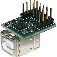
MM232R
Manufacturer Part Number
MM232R
Description
Interface Modules & Development Tools USB to Serial UART Mini Dev Mod FT232R
Manufacturer
FTDI
Type
Development Moduler
Specifications of MM232R
Interface Type
USB, Serial, UART
Data Bus Width
Serial
Operating Supply Voltage
1.8 V to 5.25 V
Product
Interface Modules
Supported Devices
FT232RQ
Svhc
No SVHC (18-Jun-2010)
Development Tool Type
Development Kit
Kit Features
Single Chip USB To Asynchronous Serial Data Transfer Interface, Entire USB Protocol Handled
Rohs Compliant
Yes
Supported Families
FT232RQ
Tool / Board Applications
USB To Serial UART Converter
For Use With/related Products
FT232R
Lead Free Status / RoHS Status
Lead free / RoHS Compliant
Other names
626-DLP-MM232R


6
6.1 BUS Powered Configuration
Figure 6.1 Bus Powered Configuration
Figure 7.1 illustrates the MM232R in a typical USB bus powered design configuration. This is done by
connecting pin 15 (USBPWR) to pin 14 (VCC50). Pin 3 (VCCIO), the supply to the FT232RQ‟s UART and
CBUS IO pins, is connected to pin 2 (VCC). Doing this will make the UART and CBUS IO pins drive out at 5V
levels. A USB Bus Powered device gets its power from the USB bus. Basic rules for USB Bus power devices
are as follows –
i)
ii) On USB Suspend the device must draw no more than 500μA.
iii) A Bus Powered High Power USB Device (one that draws more than 100mA) should use PWREN# to
iv) A device that consumes more than 100mA cannot be plugged into a USB Bus Powered Hub.
v) No device can draw more that 500mA from the USB Bus.
The Figure also illustrates interfacing the MM232R module to a microcontroller (MCU) UART interface.
This example uses TXD and RXD for transmission and reception of data, and RTS# / CTS# hardware
handshaking. Also in this example the 12MHz clock output on pin 9 is used to clock the MCU. If the
MCU is handling power management functions, then this can be done by connecting PWREN# to an I/O
pin on the MCU.
© Copyright 2010 Future Technology Devices International Ltd
On plug-in to USB, the device must draw no more than 100mA.
keep the current below 100mA on plug-in and 500μA on USB suspend.
Module Configurations
MM232R USB - Serial UART Development Module Incorporating Clock Generator
Document Reference No.: FT_000214
Clearance No.: FTDI# 132
Datasheet Version 1.1
13
Related parts for MM232R
Image
Part Number
Description
Manufacturer
Datasheet
Request
R

Part Number:
Description:
Interface Modules & Development Tools USB to Serial UART MiniB Dev Mod FT232R
Manufacturer:
FTDI
Datasheet:

Part Number:
Description:
BOARD, EVALUATION, EU PSU
Manufacturer:
FTDI
Datasheet:
Part Number:
Description:
BOARD, EVALUATION, UK PSU
Manufacturer:
FTDI
Datasheet:
Part Number:
Description:
BOARD, EVALUATION, US PSU
Manufacturer:
FTDI
Datasheet:
Part Number:
Description:
Specifications: Manufacturer: FTDI ; Product Category: USB Interface IC ; RoHS: Details ; Operating Supply Voltage: 3 V to 5.25 V ; Supply Current: 25 mA ; Maximum Operating Temperature: + 70 C ; Mounting Style: SMD/SMT ; Package / Case: QFN-32
Manufacturer:
FTDI
Part Number:
Description:
integr. usb2.0/uart lqfp32 rohs ftdi reel c1k...
Manufacturer:
FTDI
Datasheet:
Part Number:
Description:
Interface Development Tools USB to UART Breakout Board
Manufacturer:
FTDI
Datasheet:

Part Number:
Description:
IC USB TO SERIAL UART 32-QFN
Manufacturer:
FTDI, Future Technology Devices International Ltd

Part Number:
Description:
USB Interface IC USB to Serial UART Enhanced IC SSOP-28
Manufacturer:
FTDI
Datasheet:

Part Number:
Description:
IC, USB UART INTERFACE, SSOP-28
Manufacturer:
FTDI
Datasheet:

Part Number:
Description:
IC, USB UART INTERFACE, QFN-32
Manufacturer:
FTDI
Datasheet:
Part Number:
Description:
IC, USB FIFO INTERFACE, SSOP-28
Manufacturer:
FTDI
Datasheet:
Part Number:
Description:
MODULE, USB, 4 PORT, FT4232H BASED
Manufacturer:
FTDI
Datasheet:
Part Number:
Description:
357-036-542-201 CARDEDGE 36POS DL .156 BLK LOPRO
Manufacturer:
FTDI
Datasheet:
Part Number:
Description:
357-036-542-201 CARDEDGE 36POS DL .156 BLK LOPRO
Manufacturer:
FTDI
Datasheet: