EVALST7590-1 STMicroelectronics, EVALST7590-1 Datasheet - Page 16
EVALST7590-1
Manufacturer Part Number
EVALST7590-1
Description
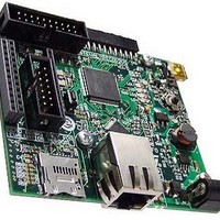
Power Management Modules & Development Tools ST7590 PRIME BRD Narrow-Band OFDM
Manufacturer
STMicroelectronics
Type
Motor / Motion Controllers & Driversr
Datasheet
1.EVALST7590-1.pdf
(43 pages)
Specifications of EVALST7590-1
Interface Type
Ethernet
Product
Power Management Development Tools
For Use With/related Products
ST7590
Lead Free Status / RoHS Status
Lead free / RoHS Compliant


Configuration
5.12
5.12.1
5.12.2
16/43
Wi-Fi optional modules
There are two positions for optional Wi-Fi modules:
Table 14.
Wi-Fi optional module-1 U9 settings
Table 15.
Wi-Fi optional module-2 U10 settings and signal description
Table 16.
U10 - module-2
GPIO4 - SD_CMD
(3-pin resistor)
(3-pin resistor)
GPIO9 - SD_CLK
U9 - module-1
GPIO5 - SD_D0
GPIO6 - SD_D1
GPIO7 - SD_D2
Signal on U10
GPIO8 - SD_3
Position
Jumper
JP4
JP5
Optional Wi-Fi modules configuration
Wi-Fi optional module-1 U9 settings
Wi-Fi optional module-2 U10 settings and signal description
JTGENPB7 is pulled to GND.
The jumper with resistance of 10 kΩ must be set as
shown:
JTGENPB7 is pulled to +3.3 V.
The jumper with resistance of 10 kΩ must be set as
shown:
JTGRNPB6 is pulled to GND.
The jumper with resistance of 10 kΩ must be set as
shown:
JTGTN is pulled to +3.3 V.
The jumper with resistance of 10 kΩ must be set as
shown:
SPI1 + CS_Wi-Fi
Interface used
SDIO description
USART1
Doc ID 17009 Rev 1
SCK
IRQ
DO
NC
CS
DI
Description
These signals are shared with I
extension connector, refer to
JP2, JP3 must be configured accordingly.
SPI description
MOSI
MISO
SCK
SS
—
—
Note
Section
STM32 SPI signals
2
C for MEMS
Configuration
SCS_N
5.6.
MOSI
MISO
SCK
—
—
UM0896
Related parts for EVALST7590-1
Image
Part Number
Description
Manufacturer
Datasheet
Request
R

Part Number:
Description:
STMicroelectronics [RIPPLE-CARRY BINARY COUNTER/DIVIDERS]
Manufacturer:
STMicroelectronics
Datasheet:
Part Number:
Description:
STMicroelectronics [LIQUID-CRYSTAL DISPLAY DRIVERS]
Manufacturer:
STMicroelectronics
Datasheet:

Part Number:
Description:
BOARD EVAL FOR MEMS SENSORS
Manufacturer:
STMicroelectronics
Datasheet:
Part Number:
Description:
NPN TRANSISTOR POWER MODULE
Manufacturer:
STMicroelectronics
Datasheet:
Part Number:
Description:
TURBOSWITCH ULTRA-FAST HIGH VOLTAGE DIODE
Manufacturer:
STMicroelectronics
Datasheet:
Part Number:
Description:
Manufacturer:
STMicroelectronics
Datasheet:
Part Number:
Description:
DIODE / SCR MODULE
Manufacturer:
STMicroelectronics
Datasheet:
Part Number:
Description:
DIODE / SCR MODULE
Manufacturer:
STMicroelectronics
Datasheet:
Part Number:
Description:
Search -----> STE16N100
Manufacturer:
STMicroelectronics
Datasheet:
Part Number:
Description:
Search ---> STE53NA50
Manufacturer:
STMicroelectronics
Datasheet:
Part Number:
Description:
NPN Transistor Power Module
Manufacturer:
STMicroelectronics
Datasheet:
Part Number:
Description:
DIODE / SCR MODULE
Manufacturer:
STMicroelectronics
Datasheet: