EZLC4432B1-D470 Silicon Laboratories Inc, EZLC4432B1-D470 Datasheet - Page 3
EZLC4432B1-D470
Manufacturer Part Number
EZLC4432B1-D470
Description
RF Modules & Development Tools EZLink Kit F930 Si4432 Rev B1 470MHz
Manufacturer
Silicon Laboratories Inc
Datasheet
1.EZLC4431B1-D434.pdf
(24 pages)
Specifications of EZLC4432B1-D470
Product
RF Development Tools
Maximum Frequency
470 MHz
Supply Voltage (max)
3.3 V
For Use With/related Products
Si4432, C8051F930
Lead Free Status / RoHS Status
Lead free / RoHS Compliant


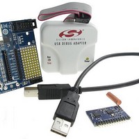
3. Functional Description
The radio modules contain the RF transceiver, a 50 matching circuit for the 915/868 MHz*, the necessary
external components (quartz crystal, power supply decoupling capacitors, etc.) and a small spiral antenna.
The module also contains a microcontroller for configuring and controlling the radio. The power, programming pins
and some of the available I/O connections are available via the connector and routed to the peripheral board for
easy access.
*Note: In order to operate at 434 MHz, matching network values are published on the schematics (See Figure 9, “EZLink Radio
The peripheral board is designed to provide access to commonly used interfaces such as battery, USB, and debug
connections. For prototyping purposes the peripheral board also has LEDs, a push button, and test points. To help
with the module orientation, the module’s connector is keyed and the silkscreen has a white triangle to point to the
antenna end.
Note: The white triangle is used to denote the correct orientation of the module and the peripheral board.
Module Schematic (Si4421/C8051F930),” on page 14 and Figure 12, “EZLink Radio Module Schematic (Si443x/
C8051F930),” on page 21).
Figure 2. EZLink Main Board
Rev. 0.1
E Z L i n k U G
3
Related parts for EZLC4432B1-D470
Image
Part Number
Description
Manufacturer
Datasheet
Request
R

Part Number:
Description:
SMD/C°/SINGLE-ENDED OUTPUT SILICON OSCILLATOR
Manufacturer:
Silicon Laboratories Inc
Part Number:
Description:
Manufacturer:
Silicon Laboratories Inc
Datasheet:
Part Number:
Description:
N/A N/A/SI4010 AES KEYFOB DEMO WITH LCD RX
Manufacturer:
Silicon Laboratories Inc
Datasheet:
Part Number:
Description:
N/A N/A/SI4010 SIMPLIFIED KEY FOB DEMO WITH LED RX
Manufacturer:
Silicon Laboratories Inc
Datasheet:
Part Number:
Description:
N/A/-40 TO 85 OC/EZLINK MODULE; F930/4432 HIGH BAND (REV E/B1)
Manufacturer:
Silicon Laboratories Inc
Part Number:
Description:
EZLink Module; F930/4432 Low Band (rev e/B1)
Manufacturer:
Silicon Laboratories Inc
Part Number:
Description:
I°/4460 10 DBM RADIO TEST CARD 434 MHZ
Manufacturer:
Silicon Laboratories Inc
Part Number:
Description:
I°/4461 14 DBM RADIO TEST CARD 868 MHZ
Manufacturer:
Silicon Laboratories Inc
Part Number:
Description:
I°/4463 20 DBM RFSWITCH RADIO TEST CARD 460 MHZ
Manufacturer:
Silicon Laboratories Inc
Part Number:
Description:
I°/4463 20 DBM RADIO TEST CARD 868 MHZ
Manufacturer:
Silicon Laboratories Inc
Part Number:
Description:
I°/4463 27 DBM RADIO TEST CARD 868 MHZ
Manufacturer:
Silicon Laboratories Inc
Part Number:
Description:
I°/4463 SKYWORKS 30 DBM RADIO TEST CARD 915 MHZ
Manufacturer:
Silicon Laboratories Inc
Part Number:
Description:
N/A N/A/-40 TO 85 OC/4463 RFMD 30 DBM RADIO TEST CARD 915 MHZ
Manufacturer:
Silicon Laboratories Inc
Part Number:
Description:
I°/4463 20 DBM RADIO TEST CARD 169 MHZ
Manufacturer:
Silicon Laboratories Inc