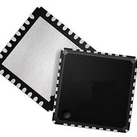
73M1906B-IVT/F Maxim Integrated Products, 73M1906B-IVT/F Datasheet - Page 45

73M1906B-IVT/F
Manufacturer Part Number
73M1906B-IVT/F
Description
Interface - Specialized DAA-FXO VolP SYSTEM HOST SIDE
Manufacturer
Maxim Integrated Products
Type
MicroDAA with PCM Highwayr
Datasheet
1.73M1866B-KEYCHN.pdf
(88 pages)
Specifications of 73M1906B-IVT/F
Operating Supply Voltage
3.3 V
Maximum Operating Temperature
+ 85 C
Minimum Operating Temperature
- 40 C
Mounting Style
SMD/SMT
Package / Case
QFN-32
Lead Free Status / RoHS Status
Lead free / RoHS Compliant
Available stocks
Company
Part Number
Manufacturer
Quantity
Price
Company:
Part Number:
73M1906B-IVT/F
Manufacturer:
LT
Quantity:
121
DS_1x66B_001
8 PCM Highway Interface and Signal Processing
The PCM highway is the method by which the 73M1x66B exchanges PCM data with the host or other
PCM-enabled devices. The PCM data can be in either 8-bit compressed mode or in 16-bit linear mode.
Compression of the received signals from the PSTN line interface is selectable A-law or μ-law, as
specified by ITU-T Recommendation G.711. The 73M1x66B is configurable with respect to tuning the
clock and time slot relationships. See Section 8.1 for details.
The PCM interface provided by the 73M1x66B consists of the following signals:
•
•
•
•
The basic timing relationship of PCM highway interface signals is shown in Figure 20.
8.1
Signal FS defines the frame boundaries by being asserted at a rate of 8 kHz. The duration of FS is
defined by the setup and hold times around the falling edge of PCLK and can be extended to multiple
PCLK cycles. The timing relationship between FS and PCLK is determined by the rising edge of FS and
the first falling edge of PCLK that follows the FS rising edge. PCLK and FS are common to all devices
connected to the PCM highway. The ratio of PCLK frequency to FS frequency determines the number of
bit slots available during a frame, i.e., the number of bits per frame. The number of bit slots divided by 8
is the number of 8-bit time slots available during the frame.
Refined granularity to the time slot can be achieved by programming the clock slot offset. The clock slot
defines an offset in terms of the number of bits from the start of the time slot. The combination of the
transmit and receive time slot and clock slot registers determines the bit slot at which the 73M1x66B
begins transmitting or receiving a data sample. Adjustments of a half clock period can be made using
these controls in conjunction with TPOL and RPOL.
The 73M1x66B supports a 16-bit linear transmission and receive mode. The transmission and reception
of the data samples consumes two adjacent 8-bit time slots each on the PCM highway. The 16-bit data
sample is transmitted most significant bit first starting at the bit slot defined by the TTS and TCS controls.
The transmission lasts for 16 consecutive bit slots, as illustrated in Figure 21.
Rev. 1.6
PCLK Frequency
FS
Frequency (8 kHz)
PCLK
FS
DX
DR
PCLK
PCM Highway Interface Timing
DX
FS
The frequency at which bits are driven on the PCM highway. (Goes to the PCLKI pin.)
PCM frame synchronization pulse.
PCM data transmitted to the PCM highway.
PCM data received from the PCM highway.
= Bits per Frame
MSB
Figure 20: 8-bit Transmission Example
Bits per Frame
8-bits per Time Slot
LSB
= Number of Time Slots per Frame
73M1866B/73M1966B Data Sheet
45


