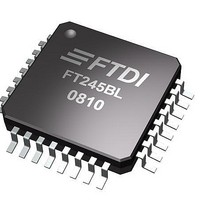
FT245BL-REEL FTDI, FT245BL-REEL Datasheet - Page 6

FT245BL-REEL
Manufacturer Part Number
FT245BL-REEL
Description
USB Interface IC USB to Parallel FIFO IC LQFP-32
Manufacturer
FTDI
Type
USB to Parallel FIFOr
Datasheet
1.FT245BL-REEL.pdf
(24 pages)
Specifications of FT245BL-REEL
Mounting Style
SMD/SMT
Package / Case
LQFP
Operating Supply Voltage
3 V to 5.25 V
Description/function
USB to Parallel FIFO IC LQFP-32
Maximum Operating Temperature
+ 70 C
Minimum Operating Temperature
0 C
Operating Temperature Range
0 C to + 70 C
Supply Current
25 mA
Lead Free Status / RoHS Status
Lead free / RoHS Compliant
Available stocks
Company
Part Number
Manufacturer
Quantity
Price
Company:
Part Number:
FT245BL-REEL
Manufacturer:
FTDI, Future Technology Devices International Ltd
Quantity:
10 000
•
•
•
•
•
•
Serial Interface Engine (SIE)
USB Protocol Engine
FIFO Receive Buffer (128 bytes)
FIFO Transmit Buffer (384 bytes)
FIFO Controller
RESET Generator
DS245BL Version 1.7
The Serial Interface Engine (SIE) block performs
the Parallel to Serial and Serial to Parallel
conversion of the USB data. In accordance to the
USB 2.0 specification, it performs bit stuffing / un-
stuffing and CRC5 / CRC16 generation / checking
on the USB data stream.
The USB Protocol Engine manages the data
stream from the device USB control endpoint. It
handles the low level USB protocol (Chapter 9)
requests generated by the USB host controller
and the commands for controlling the functional
parameters of the FIFO.
Data sent from the USB Host to the FIFO via
the USB data out endpoint is stored in the FIFO
Receive Buffer and is removed from the buffer by
reading the FIFO contents using RD#.
Data written into the FIFO using WR# is stored in
the FIFO Transmit Buffer. The Host removes Data
from the FIFO Transmit Data by sending a USB
request for data from the device data in endpoint.
The FIFO Controller handles the transfer of data
between the external FIFO interface pins and the
FIFO Transmit and Receive buffers.
The Reset Generator Cell provides a reliable
power-on reset to the device internal circuitry
on power up. An additional RESET# input and
RSTOUT# output are provided to allow other
devices to reset the FT245BL, or the FT245BL
to reset other devices respectively. During reset,
RSTOUT# is driven low, otherwise it drives out
at the 3.3V provided by the onboard regulator.
RSTOUT# can be used to control the 1.5K
pull-up on USBDP directly where delayed USB
© Future Technology Devices Intl. Ltd. 2005
•
EEPROM Interface
FT245BL USB FIFO ( USB - Parallel ) I.C.
enumeration is required. RSTOUT# will be low for
approximately 5ms after VCC has risen above 3.5V
AND the device oscillator is running AND RESET#
is high. RESET# should be tied to VCC unless it
is a requirement to reset the device from external
logic or an external reset generator I.C.
Though the FT245BL will work without the optional
EEPROM, an external 93C46 (93C56 or 93C66)
EEPROM can be used to customise the USB VID,
PID, Serial Number, Product Description Strings
and Power Descriptor value of the FT245BL for
OEM applications. Other parameters controlled
by the EEPROM include Remote Wake Up,
Isochronous Transfer Mode, Soft Pull Down on
Power-Off and USB 2.0 descriptor modes.
The EEPROM should be a 16 bit wide
configuration such as a MicroChip 93LC46B or
equivalent capable of a 1Mb/s clock rate at VCC =
4.35V to 5.25V. The EEPROM is programmable-
on board over USB using a utility available from
FTDI’s web site (
allows a blank part to be soldered onto the PCB
and programmed as part of the manufacturing and
test process.
If no EEPROM is connected (or the EEPROM is
blank), the FT245BL will use its built-in default VID,
PID Product Description and Power Descriptor
Value. In this case, the device will not have a serial
number as part of the USB descriptor.
http://www.ftdichip.com
Page 6 of 24
). This


