10-101949-012 Amphenol Industrial Operations, 10-101949-012 Datasheet - Page 41
10-101949-012
Manufacturer Part Number
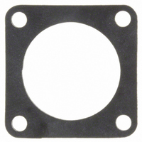
10-101949-012
Description
SEALING GASKET FOR #12 WALL RCPT
Manufacturer
Amphenol Industrial Operations
Series
MIL-DTL-26482 Series I, PTr
Specifications of 10-101949-012
Accessory Type
Flange Gasket
Shell Size - Insert
12
Brand/series
PT and PC Series
For Use With/related Products
MIL-C-26482, Series 1 PT and PC Receptacle
For Use With
PT00E-12-10S - CONN RCPT 10 POS WALL MNT W/SCKTPT00A-12-10S - CONN RCPT 10 POS WALL MNT W/SCKTPT00A-12-10P - CONN RCPT 10 POS WALL MNT W/PINSPT02SE12-10S(025) - CONN RECEPT 10POS W/SOCKET CRIMPPT02SE12-10P(025) - CONN RECEPT 10POS W/PINS CRIMPPT02E-12-8P(025) - CONN RECEPT 8POS W/PINS SOLDERPT02E-12-4S(025) - CONN RECEPT 4POS W/SOCKET SOLDERPT02E-12-3P(025) - CONN RECEPT 3POS W/PINS SOLDERPT02E-12-10S(025) - CONN RECEPT 10POS W/SOCKT SOLDERPT02E-12-10P(025) - CONN RECEPT 10POS W/PINS SOLDERPT02A12-3S(025) - CONN RECEPT 3POS W/SOCKET SOLDERPT02A12-3P(025) - CONN RECEPT 3POS W/PINS SOLDERPT02A12-10S(025) - CONN RECEPT 10POS W/SOCKT SOLDERPT02A12-10P(025) - CONN RECEPT 10POS W/PINS SOLDERPT02E-12-8P - CONN RECEPT 8POS W/PINS SOLDERPT02E-12-4S - CONN RECEPT 4POS W/SOCKET SOLDERPT02E-12-3P - CONN RECEPT 3POS W/PINS SOLDERPT02E-12-10S - CONN RECEPT 10POS W/SOCKT SOLDERPT02E-12-10P - CONN RECEPT 10POS W/PINS SOLDERAMS3122E-12-10S - CONN RECEPT 10POS W/SOCKET CRIMPAMS3112E-12-3S - CONN RECEPT 3POS W/SOCKET SOLDERAMS3112E-12-10S - CONN RECEPT 10POS W/SOCKT SOLDERPT02SE12-10P - CONN RECEPT 10POS W/PINS CRIMPPT02SE12-10S - CONN RECEPT 10POS W/SOCKET CRIMPPT02A12-10P - CONN RECEPT 10POS W/PINS SOLDERPT02A12-10S - CONN RECEPT 10POS W/SOCKT SOLDERPT02A12-3P - CONN RECEPT 3POS W/PINS SOLDERPT02A12-3S - CONN RECEPT 3POS W/SOCKET SOLDER
Lead Free Status / RoHS Status
Lead free / RoHS Compliant
Features
-
Color
-


PT-SE, SP-SE, MS/PT-SE
how to order
PT-SE, SP-SE
To more easily illustrate ordering procedure, part number PT00SE-20-
41PW(SR) is shown as follows:
See code below:
1. Connector Type
2. Shell Style
3. Service Classes
4. Shell Size
5. Insert Arrangement
6. Contacts
7. Insert Rotation
8. “SR” designates a strain relief clamp.
PT
1
“PT”
“MF”
“SP”
“PTG” designates plug with grounding fingers
“00”
“01”
“02”
“06”
“07”
“08”
“SE”
“SP”
Both of the above are Amphenol proprietary versions of the MIL-C-
26482, Series 1 crimp contact connector and offer 15 lbs. contact reten-
tion for size 20 contacts; 25 lbs. for size 16 contacts.
“20” designates shell size. Shell sizes 8 through 24 available.
Refer to pages 4-11 for insert availability.
“20 - 41” designates insert arrangement. (The number following the
hyphen is the number only that is used in the part number).
“P” designates pin contacts
“S” designates socket contacts
Refer to page 7.
“W”, “X”, “Y”, “Z” designate that insert is rotated in its shell from “normal”
position. No letter required for normal (no rotation) position.
Indicate optional finishes as follows:
(003)
(005)
(014)
(023)
(024)
(424)
(466)
OR
RoHS Compliant finish suffix as follow:
(025)
(027)
(470)
(476)
00
2
designates standard olive drab, electrically conductive cadmium
plated, bayonet lock connector with crimp contacts
designates standard olive drab, electrically conductive cadmium
plated, bayonet lock connector with dual mounting holes, and
crimp contacts
designates electrically non-conductive, hard anodic coated,
bayonet lock connector with larger flange and mounting holes
for back panel mounting, and crimp contacts
designates wall mounting receptacle
designates cable connecting receptacle*
designates box mounting receptacle
designates straight plug
designates jam nut receptacle
designates 90 degree plug
designates environmental crimp
designates potted type crimp
olive drab cadmium plate (standard on “PT”)
anodic coating - Alumilite
olive drab cadmium plate over nickel
electroless nickel
olive drab zinc cobalt plating
electroless nickel finish with strain relief
olive drab zinc cobalt plating with strain relief
non-conductive black zinc cobalt plating
conductive black zinc cobalt plating
non-conductive black zinc cobalt plating with
strain relief
conductive black zinc cobalt with strain relief
SE - 20 - 41
3
4
5
®
P
6
(standard on “SP”)
W
7
(SR)
8
39
MS/PT-SE
MIL-C-26482, Series 1
To more easily illustrate ordering procedure, part number
MS3120E20-41PW is shown as follows:
See code below:
1. “MS” designates Military Standard
2. Specification Number
3. Shell Style
4. Service Class
5. Shell Size
6. Insert Arrangement
7. Contacts
8. Insert Rotation
* This connector style is sometimes referred to as a cable connecting
For ordering Miniature Breakaway PT-SE Crimp connectors
see pg. 38.
MS
1
“plug”. It does, however, mate with either a straight or 90 degree plug.
“312” designates basic family for MIL-C-26482, Series 1
crimp type
“0”
“1”
“2”
“4”
“6”
“7”
“8”
“E”
“F”
“P”
“20” designates shell size. Shell sizes 8 through 24 available
Refer to pages 4-11 for insert availability.
“20 - 41” designates insert arrangement. (The number follow-
ing the hyphen is the number only that is used in the part
number).
“P” designates pin contacts
“S” designates socket contacts
Refer to page 7.
“W”, “X”, “Y”, “Z” designate that insert is rotated in its shell
from the “normal” position. No letter required for normal (no
rotation) position.
312
2
designates wall mounting receptacle
designates cable connecting receptacle*
designates box mounting receptacle
designates jam nut receptacle
designates straight plug
designates box mounting receptacle with dual
mounting holes
designates wall mounting receptacle with dual
mounting holes
designates environmental resisting connector
designates environmental resisting connector with
strain relief
designates potted type with potting boot
0
3
E
4
20 – 41
5
6
P
7
W
8
Related parts for 10-101949-012
Image
Part Number
Description
Manufacturer
Datasheet
Request
R

Part Number:
Description:
SOCKET, PCB, 0.2", 6WAY
Manufacturer:
Molex Inc
Datasheet:
Part Number:
Description:
SOCKET, PCB, 0.2", 8WAY
Manufacturer:
Molex Inc
Datasheet:

Part Number:
Description:
Header Connector,PCB Mount,PLUG,3 Contacts,SKT,0.2 Pitch,PC TAIL Terminal
Manufacturer:
Molex Inc
Datasheet:

Part Number:
Description:
Header Connector,PCB Mount,PLUG,5 Contacts,SKT,0.2 Pitch,PC TAIL Terminal
Manufacturer:
Molex Inc
Datasheet:
Part Number:
Description:
Header Connector,PCB Mount,PLUG,7 Contacts,SKT,0.2 Pitch,PC TAIL Terminal
Manufacturer:
Molex Inc
Datasheet:

Part Number:
Description:
JAM NUT CONN, RCPT, SIZE 9, 6POS, PANEL
Manufacturer:
Amphenol Industrial Operations
Datasheet:

Part Number:
Description:
PT 41C 41#20 PIN RECP
Manufacturer:
Amphenol Industrial Operations
Part Number:
Description:
PT 41C 41#20 SKT RECP
Manufacturer:
Amphenol Industrial Operations