NTE6409 NTE ELECTRONICS, NTE6409 Datasheet - Page 2
NTE6409
Manufacturer Part Number
NTE6409
Description
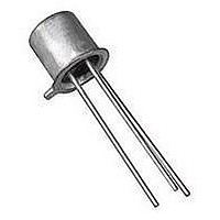
Replacement Semiconductors TO-18 UNIJUNCT TRANS
Manufacturer
NTE ELECTRONICS
Datasheet
1.NTE6409.pdf
(2 pages)
Specifications of NTE6409
Repetitive Peak Forward Current Itrm
2A
Peak Emitter Current
1µA
Valley Current Iv
10mA
Power Dissipation Pd
300mW
Operating Temperature Range
-65°C To +125°C
No. Of Pins
2
Lead Free Status / RoHS Status
Lead free / RoHS Compliant
Lead Free Status / RoHS Status
Lead free / RoHS Compliant, Lead free / RoHS Compliant


Electrical Characteristics: (T
Note 3. Intrinsic Standoff Ratio, , is defined by the equation:
Note 4. Use pulse techniques: PW [ 300 s, Duty Cycle
Intrinsic Standoff Ratio
Interbase Resistance
Interbase Resistance
Emitter Saturation Voltage
Modulated Interbase Current I
Emitter Reverse Current
Peak Point Emitter Current
Valley Point Current
Base–One Peak Pulse
Temperature Coefficient
Voltage
Parameter
base modulation which may result in erroneous readings.
Where: V
V
V
P
B2B1
F
=
= Emitter to Base–One Junction Diode Drop ([ 0.45V @ 10 A)
= Peak Point Emitter Voltage
V
V
P
= Interbase Voltage
B2B1
– V
V
Symbol
F
B2(mod)
EB1(sat)
I
V
EB2O
r
OB1
BB
r
I
I
A
P
V
BB
= +25 C unless otherwise specified)
Emitter
.210 (5.33)
V
V
V
V
V
V
V
V
(12.7)
B2B1
.500
B2B1
B2B1
B2B1
B2B1
B2E
B2B1
B2B1
Max
Min
45
= 30V, I
= 3V, I
= 10V, Note 3
= 3V, I
= 10V, I
= 10V, I
= 25V
= 20V, R
.041 (1.05)
Test Conditions
E
E
B1
= 0, T
E
E
= 0
B2
= 50mA, Note 4
= 50mA
= 0
.018 (0.45)
= 100 , Note 4
A
Base 1
Base 2/Case
.230 (5.84) Dia Max
.195 (4.95) Dia Max
= –55 to +125 C
.030 (.762) Max
2% to avoid internal heating due to inter-
0.68
Min
4.7
0.1
–
–
–
–
8
6
0.005
Typ
7.0
3.5
15
10
–
–
1
7
Max Unit
0.82
9.1
0.9
0.2
18
–
–
2
–
%/ C
mA
mA
k
V
V
A
A
Related parts for NTE6409
Image
Part Number
Description
Manufacturer
Datasheet
Request
R

Part Number:
Description:
TRANSISTOR,BJT,NPN,15V V(BR)CEO,30MA I(C),SOT-100
Manufacturer:
NTE ELECTRONICS
Datasheet:

Part Number:
Description:
ICS,NTE LED FLASHLIGHTS,ICS,RED TRAFFIC AND SAFETY WAND FOR LW-PRO4000-BLK. MOLDED TRANSLUCENT PLASTIC WAND,TASK LIGHTING,LIGHTWAVE? LED FLASHLIGHTS ,NTE ELECTRONICS
Manufacturer:
NTE ELECTRONICS

Part Number:
Description:
Fuse; Non-Resettable; 15A; Dims 0.16x0.457"; Axial; 120-277VAC; PCB; NTE Series
Manufacturer:
NTE Electronics, Inc.
Datasheet:
Part Number:
Description:
Fuse; Non-Resettable; 15A; Dims 0.16x0.457"; Axial; 120-277VAC; PCB; NTE Series
Manufacturer:
NTE Electronics, Inc.
Datasheet:
Part Number:
Description:
Fuse; Non-Resettable; 15A; Dims 0.16x0.457"; Axial; 120-277VAC; PCB; NTE Series
Manufacturer:
NTE Electronics, Inc.
Datasheet:
Part Number:
Description:
Fuse; Non-Resettable; 15A; Dims 0.16x0.457"; Axial; 120-277VAC; PCB; NTE Series
Manufacturer:
NTE Electronics, Inc.
Datasheet:
Part Number:
Description:
Fuse; Non-Resettable; 15A; Dims 0.16x0.457"; Axial; 120-277VAC; PCB; NTE Series
Manufacturer:
NTE Electronics, Inc.
Datasheet:
Part Number:
Description:
Fuse; Non-Resettable; 15A; Dims 0.16x0.457"; Axial; 120-277VAC; PCB; NTE Series
Manufacturer:
NTE Electronics, Inc.
Datasheet:
Part Number:
Description:
Fuse; Non-Resettable; 15A; Dims 0.16x0.457"; Axial; 120-277VAC; PCB; NTE Series
Manufacturer:
NTE Electronics, Inc.
Datasheet:
Part Number:
Description:
Fuse; Non-Resettable; 15A; Dims 0.16x0.457"; Axial; 120/250VAC; PCB; NTE Series
Manufacturer:
NTE Electronics, Inc.
Datasheet:
Part Number:
Description:
MOTOR START AC ELECTROLYTIC
Manufacturer:
NTE [NTE Electronics]
Datasheet:
Part Number:
Description:
SOLID TANTALUM
Manufacturer:
NTE [NTE Electronics]
Datasheet:
Part Number:
Description:
HIGH-FREQ ALUMINUM ELECTROLYTIC
Manufacturer:
NTE [NTE Electronics]
Datasheet:
Part Number:
Description:
SNAP-IN MOUNT ALUMINUM ELECTROLYTIC
Manufacturer:
NTE [NTE Electronics]
Datasheet:

Part Number:
Description:
Replacement Semiconductors TO-220 NPN PWR AMP
Manufacturer:
NTE ELECTRONICS
Datasheet: