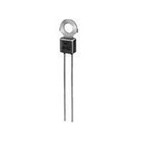
PTFM04BG222Q2N34B0 Murata, PTFM04BG222Q2N34B0 Datasheet - Page 98

PTFM04BG222Q2N34B0
Manufacturer Part Number
PTFM04BG222Q2N34B0
Description
Thermistors - PTC 2.2K OHM 20%
Manufacturer
Murata
Type
PTCr
Series
PTFMr
Datasheet
1.PRF21BA471QB1RA.pdf
(100 pages)
Specifications of PTFM04BG222Q2N34B0
Resistance
330 Ohms
Tolerance
20 %
Termination Style
Radial
Operating Temperature Range
- 10 C to + 130 C
Current Rating
0.1 Amp
Dimensions
4 mm Dia.
Voltage
16 V
Thermistor Type
PTC
Operating Voltage Range
16V
Thermistor Case Style
Radial Leaded
No. Of Pins
2
Length/height, External
13.2mm
External Width
7.5mm
Rohs Compliant
Yes
Lead Free Status / RoHS Status
Lead free / RoHS Compliant
12
!Note
96
Lead Type PTGL/PTF Series Package
Narrow Current Band 30 - 140V Series / 16 - 80V Series Taping Dimensions
Continued from the preceding page.
• Please read rating and !CAUTION (for storage, operating, rating, soldering, mounting and handling) in this catalog to prevent smoking and/or burning, etc.
• This catalog has only typical specifications because there is no space for detailed specifications. Therefore, please review our product specifications or consult the approval sheet for product specifications before ordering.
Pitch of Component
Pitch of Sprocket Hole
Lead Spacing
Length from Hole Center to Lead
Length from Hole Center to Component Center
Body Diameter
Body Thickness
Deviation along Tape, Left or Right Defect
Carrier Tape Width
Position of Sprocket Hole
Lead Distance between Reference and
Bottom Planes
Protrusion Length
Diameter of Sprocket Hole
Lead Diameter
Total Tape Thickness
Total Thickness of Tape and Lead Wire
Deviation across Tape
Portion to cut in Case of Defect
Hold down Tape Width
Hold down Tape Position
Coating Extension on Lead
Item
Code
h
W
1
W
W
H
H
D
P
P
P
W
P
F
D
T
t
t
d
, h
L
e
I
1
2
S
0
1
2
0
2
0
1
0
2
P
P
1
2
2
P
F
0
D
Up to the center of crimp
Please see in Ratings
Please see in Ratings
Please see in Ratings
P
Dimensions (mm)
W0.5 to Y1.0
d
11.0
11.0 min.
12.7 0.3
3.85 0.8
6.35 1.3
18.0 0.5
16.0 1.0
6.0 max.
2.0 max.
1.5 max.
4.0 max.
5.0
9.0
4.0 0.2
0.6 0.3
12.7
S
1.5
+0.8
–0.3
+0.5
–0.75
+0
–2.0
h
T
1
Tolerance is determined by S.
Deviation in the feeding direction
Including the inclination caused by lead bending
Deviation of tape width
h
2
Note
Continued on the following page.
Apr.25,2011
R90E.pdf


