RPER71H104K2M1A03A Murata, RPER71H104K2M1A03A Datasheet - Page 5
RPER71H104K2M1A03A
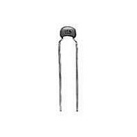
Manufacturer Part Number
RPER71H104K2M1A03A
Description
Multilayer Ceramic Capacitors (MLCC) - Leaded 0.1uF 50volts X7R 10% 5.0mm L/S
Manufacturer
Murata
Series
RPEr
Datasheet
1.RPER71H104K2M1A03A.pdf
(14 pages)
Specifications of RPER71H104K2M1A03A
Voltage Rating
50 Volts
Termination Style
Radial
Operating Temperature Range
- 55 C to + 125 C
Product
General Type MLCCs
Dimensions
3.5 mm W x 5 mm L
Capacitance
0.1 uF
Tolerance
10 %
Temperature Coefficient
X7R
Lead Spacing
5 mm
Lead Free Status / RoHS Status
Lead free / RoHS Compliant


3
!Note
• This PDF catalog is downloaded from the website of Murata Manufacturing co., ltd. Therefore, it’s specifications are subject to change or our products in it may be discontinued without advance notice. Please check with our
• This PDF catalog has only typical specifications because there is no space for detailed specifications. Therefore, please approve our product specifications or transact the approval sheet for product specifications before ordering.
sales representatives or product engineers before ordering.
!Note
20
No.
10
RH Series 150 C max. (for Automotive) Specifications and Test Methods
Specifications and Test Methods
1
2
3
4
5
6
7
8
9
Operating Temperature
Range
Appearance
Dimension and Marking
Dielectric
Strength
Insulation
Resistance
Capacitance
Dissipation Factor (D.F.)
Capacitance
Temperature
Characteristics
Terminal
Strength
Vibration
Resistance
• Please read rating and !CAUTION (for storage, operating, rating, soldering, mounting and handling) in this catalog to prevent smoking and/or burning, etc.
• This catalog has only typical specifications because there is no space for detailed specifications. Therefore, please approve our product specifications or transact the approval sheet for product specifications before ordering.
Item
Between
Terminals
Body
Insulation
Room
Temperature
High
Temperature
Tensile
Strength
Bending
Strength
Appearance No defects or abnormalities
Capacitance Within the specified tolerance
D.F.
-55 to +150˚C
No defects or abnormalities
See previous pages
No defects or abnormalities
No defects or abnormalities
CV0.047 F: 10,000M min.
C>0.047 F: 500M · F min.
C: Nominal capacitance
CV0.047 F: 100M min.
C>0.047 F: 5M · F min.
C: Nominal capacitance
Within the specified tolerance
0.025 max.
Within T15% (Temp. Range: -55 to +125 C)
Within +15/-40% (Temp. Range: +125 to +150 C)
Termination not to be broken or loosened
Termination not to be broken or loosened
0.025 max.
Specifications
Visual inspection
Visual inspection, Vernier Caliper
The capacitor should not be damaged when DC
voltage of 250% of the rated voltage is applied
between the terminations for 1 to 5 sec.
(Charge/Discharge current V 50mA)
The capacitor is placed in a
container with metal balls of 1mm
diameter so that each terminal,
short-circuit, is kept approximately
2mm from the balls as shown in
the figure, and 250% of the rated
DC voltage is impressed for 1 to 5
sec. between capacitor terminals
and metal balls.
(Charge/Discharge current
V 50mA)
The insulation resistance should be measured at
25 3 C with a DC voltage not exceeding the rated
voltage at normal temperature and humidity and within
2 min. of charging.
(Charge/Discharge current V 50mA)
The insulation resistance should be measured at
150 3 C with a DC voltage not exceeding the rated
voltage at normal temperature and humidity and within
2 min. of charging.
(Charge/Discharge current V 50mA)
The capacitance/D.F. should be measured at the
frequency of 1T0.1kHz and a voltage of
AC1T0.2V(r.m.s.)
The capacitance change should be measured after
5 min. at each specified temperature stage.
As in the figure, fix the capacitor body, apply the force
gradually to each lead in the radial direction of the
capacitor until reaching 10N and then keep the force
applied for 10T1 sec.
Each lead wire should be subjected to a force of 2.5N
and then bent 90˚ at the point of egress in one
direction. Each wire is then returned to the original
position and bent 90˚ in the opposite direction at the
rate of one bend per 2 to 3 sec.
The capacitor should be firmly soldered to the
supporting lead wire and vibrated at a frequency range
of 10 to 2000Hz, 1.5mm in total amplitude, with about
a 20 min. rate of vibration change from 10Hz to
2000Hz and back to 10Hz. Apply for a total of 6 hrs.,
2 hrs. each in 3 mutually perpendicular directions.
Step
1
2
3
4
5
F
Test Method
Continued on the following page.
Temperature (˚C)
–
150T3
-55T3
25T2
25T2
25T2
Approx. 2mm
Metal balls
C49E.pdf
10.3.8
Related parts for RPER71H104K2M1A03A
Image
Part Number
Description
Manufacturer
Datasheet
Request
R

Part Number:
Description:
Murata Microblower 20x20 DCDC Driver Board - Samples Only
Manufacturer:
Murata
Part Number:
Description:
357-036-542-201 CARDEDGE 36POS DL .156 BLK LOPRO
Manufacturer:
Murata
Datasheet:
Part Number:
Description:
Manufacturer:
Murata
Datasheet:
Part Number:
Description:
Manufacturer:
Murata
Datasheet:
Part Number:
Description:
Manufacturer:
Murata
Datasheet:
Part Number:
Description:
Manufacturer:
Murata
Datasheet:
Part Number:
Description:
Manufacturer:
Murata
Datasheet:
Part Number:
Description:
Manufacturer:
Murata
Datasheet:
Part Number:
Description:
Manufacturer:
Murata
Datasheet:
Part Number:
Description:
BLM21BD751SN1On-Board Type (DC) EMI Suppression Filters
Manufacturer:
Murata
Datasheet:
Part Number:
Description:
BLM15AG100SN1On-Board Type (DC) EMI Suppression Filters
Manufacturer:
Murata
Datasheet:
Part Number:
Description:
NFE31PT222Z1E9On-Board Type (DC) EMI Suppression Filters
Manufacturer:
Murata
Datasheet:
Part Number:
Description:
Chip Coil
Manufacturer:
Murata
Datasheet:
Part Number:
Description:
Chip Coil
Manufacturer:
Murata
Datasheet: