PLA10AN1522R0R2B Murata, PLA10AN1522R0R2B Datasheet - Page 22
PLA10AN1522R0R2B
Manufacturer Part Number
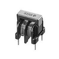
PLA10AN1522R0R2B
Description
Common Mode Inductors 2.0 AMP AC COMMON CH
Manufacturer
Murata
Series
PLA10r
Datasheets
1.PLA10AN1522R0R2B.pdf
(24 pages)
2.PLA10AN1522R0R2B.pdf
(3 pages)
3.PLA10AN1522R0R2B.pdf
(24 pages)
4.PLA10AN1522R0R2B.pdf
(24 pages)
Specifications of PLA10AN1522R0R2B
Dimensions
16 mm W x 18 mm L x 17.5 mm H
Product
Chokes
Shielding
Unshielded
Inductance
1.5 mH
Maximum Dc Current
2 Amps
Operating Temperature Range
- 25 C to + 120 C
Termination Style
Through Hole
Lead Free Status / RoHS Status
Lead free / RoHS Compliant
Available stocks
Company
Part Number
Manufacturer
Quantity
Price
Company:

Part Number:
PLA10AN1522R0R2B
Manufacturer:
TDK
Quantity:
33 000


!Note
• This PDF catalog is downloaded from the website of Murata Manufacturing co., ltd. Therefore, it’s specifications are subject to change or our products in it may be discontinued without advance notice. Please check with our
• This PDF catalog has only typical specifications because there is no space for detailed specifications. Therefore, please approve our product specifications or transact the approval sheet for product specifications before ordering.
sales representatives or product engineers before ordering.
!Note
1. Rated Current
1. Soldering Conditions
(1) Flux, Solder
(2) Flow soldering profile
For additional mounting methods, please contact Murata.
Magnetic Flux Leakage
Sn/Pb = 60/40, Sn/Pb = 63/37 Sn-3.0Ag-0.5Cu solder
Soldering temp.
240-260 C
Choke coils generate small amounts of magnetic flux
leakage that may adversely affect equipment operation
according to component arrangement.
Testing should be completed on final assembly to
ensure equipment performance is not affected.
Operating current should not exceed the rated
value. Even if operating current is under the
rated value, adequate ventilation is required to
avoid excessive heat generated within the product
(choke coil) and from surrounding heat sources.
If exceeding these conditions, excessive heat may
cause fumes or permanent damage to the product.
Please ensure that product (choke coil) is
evaluated and confirmed against the specification
when it is mounted in your final assembled product.
-> Winding temperature should be less than
*As for FKOB series winding temperature should be
less than 95 degree C.
!Caution (Rating)
Notice (Storage and Operating Condition)
Notice (Soldering and Mounting)
· Rosin-based flux should be used. Do not use strong
· Use 63/37 solder (Sn/Pb = 63/37) or 60/40 solder
120 degree C.
acidic flux with halide content exceeding 0.2wt%
(chlorine conversion value)
(Sn/Pb = 60/40). In case of lead-free solder, use
Sn-3.0Ag-0.5Cu solder
• Please read rating and !CAUTION (for storage, operating, rating, soldering, mounting and handling) in this catalog to prevent smoking and/or burning, etc.
• This catalog has only typical specifications because there is no space for detailed specifications. Therefore, please approve our product specifications or transact the approval sheet for product specifications before ordering.
Soldering time
5s max.
Standard profile
300
250
200
150
100
50
Soldering temp.
250 2 C
Pre-heating
60s min.
150 C
Soldering time
4-6s
Soldering
Soldering temperature
Soldering time
Soldering temp.
265 3 C
Gradual cooling
(in air)
Limit profile
Soldering time
5s
Cycle of flow
2 times
2. Inrush Current
If these conditions are exceeded, excessive heat may
cause fumes or permanent damage to the component,
or at worst cause ignition.
Coil Humming Noise
Magnetic flux generated between coil and core or
between the choke coil windings creates repulsive
power between the coil windings. This repulsive
power causes the coil winding to vibrate and create
a humming noise. The amount of hum produced by the
coil is proportionate to the amount of harmonic
distortion generated by the operating current. This
does not influence the electrical performance of
the coils, but it should be considered and tested
in actual circuit application.
Maximum allowable temperature at the surface of
coil (ambient temperature + winding temperature
rise) is in accordance with each safety standard
applicable to final assembled product.
When the temperature at winding exceeds maximum
allowable temperature of safety standard, the
rated current should be derated.
Inrush current should not exceed 10 times rated
current within 1/4 cycle of 50/60Hz commercial
power line. Inrush current should be limited to a
minimum of 10 seconds after last inrush.
Notice (Rating)
2. Cleaning
3. Storage and Handling Requirements
(1) Storage period
(2) Storage conditions
(3) Handling conditions
Avoid cleaning product due to non-waterproof
construction.
Product should be used within 12 months after receiving.
Solderability should be checked if this period is
exceeded.
Storage Temperature: -10 to 40 C
Relative humidity: 30 to 70%
Avoid sudden changes in temperature and humidity.
Don't keep products in corrosive gases such as sulfur,
chlorine gas or acid, or it may cause oxidation of lead
terminals resulting in poor solderability or corrosion of
component windings.
Care should be taken when transporting or handling
product to avoid excessive vibration or mechanical shock.
!Caution /Notice
C09E.pdf
21
06.2.9
2
Related parts for PLA10AN1522R0R2B
Image
Part Number
Description
Manufacturer
Datasheet
Request
R

Part Number:
Description:
Murata Microblower 20x20 DCDC Driver Board - Samples Only
Manufacturer:
Murata
Part Number:
Description:
357-036-542-201 CARDEDGE 36POS DL .156 BLK LOPRO
Manufacturer:
Murata
Datasheet:
Part Number:
Description:
Manufacturer:
Murata
Datasheet:
Part Number:
Description:
Manufacturer:
Murata
Datasheet:
Part Number:
Description:
Manufacturer:
Murata
Datasheet:
Part Number:
Description:
Manufacturer:
Murata
Datasheet:
Part Number:
Description:
Manufacturer:
Murata
Datasheet:
Part Number:
Description:
Manufacturer:
Murata
Datasheet:
Part Number:
Description:
Manufacturer:
Murata
Datasheet:
Part Number:
Description:
BLM21BD751SN1On-Board Type (DC) EMI Suppression Filters
Manufacturer:
Murata
Datasheet:
Part Number:
Description:
BLM15AG100SN1On-Board Type (DC) EMI Suppression Filters
Manufacturer:
Murata
Datasheet:
Part Number:
Description:
NFE31PT222Z1E9On-Board Type (DC) EMI Suppression Filters
Manufacturer:
Murata
Datasheet:
Part Number:
Description:
Chip Coil
Manufacturer:
Murata
Datasheet:
Part Number:
Description:
Chip Coil
Manufacturer:
Murata
Datasheet: