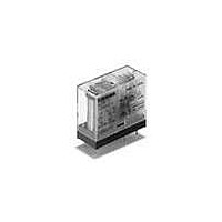
G2RG-2A4-DC24 Omron, G2RG-2A4-DC24 Datasheet - Page 2

G2RG-2A4-DC24
Manufacturer Part Number
G2RG-2A4-DC24
Description
General Purpose / Industrial Relays 1.5mm DPST-NO 24VDC
Manufacturer
Omron
Series
G2RGr
Specifications of G2RG-2A4-DC24
Contact Form
DPST - NO
Coil Voltage
24 VDC
Contact Rating
8 A at 250 VAC
Contact Termination
PCB
Mounting Style
PCB
Power Consumption
800 mW
Contact Material
Silver Alloy
Coil Current
8 A
Coil Resistance
720 Ohms
Coil Type
Non-Latching
Clearance Between Contact Terminals Of The Same Polarity
1.5 mm Min.
Conforms To Vde0435 (vde Approval
C250 Insulation Grade), UL508, CSA22.2
Tracking Resistance
CTI > 250 V
Lead Free Status / RoHS Status
Lead free / RoHS Compliant
Available stocks
Company
Part Number
Manufacturer
Quantity
Price
Company:
Part Number:
G2RG-2A4-DC24V
Manufacturer:
OMRON
Quantity:
12 000
■ Characteristics
Note: Values in the above table are the initial values, measured at an ambient temperature of 23°C
Engineering Data
Dimensions
Unit: mm (inch)
Note: The G2RG-2A4 has the same terminal arrangement as the G2R-2A4, but the switch capacity and electrical endurance are different. Confirm
138
Contact resistance
Operation time
Release time
Max. operating frequency
Insulation resistance
Dielectric strength
Impulse withstand voltage
Vibration resistance
Shock resistance
Life expectancy
Ambient temperature
Ambient humidity
Weight
DPST-NO Relays
Maximum Switching Capacity
0.5
0.1
50
10
5
1
0
that correct operation is possible in the actual operating conditions before use.
5
PCB Relay
10
30 50 100
25.5 max.
(24.7)*
Switching voltage (V)
*Figures in parentheses indicate average values.
4
AC resistive load
G2RG
300 500
0.3
29 max.
(28.6)*
0.15
0.5
100 mΩ max.
15 ms max.
5 ms max.
Mechanical: 18,000 operations/hr.
Electrical: 1,800 operations/hr. (under rated load)
1,000 MΩ min. (at 500 VDC)
5,000 VAC, 50/60 Hz for 1 min. between coil and contacts
3,000 VAC, 50/60 Hz for 1 min. between contacts of different polarity
1,000 VAC, 50/60 Hz for 1 min. between contacts of same polarity
10,000 V (1.2 x 50 μS) between coil and contacts.
Destruction: 10 to 55 Hz, 1.5-mm double amplitude
Malfunction: 10 to 55 Hz, 1.5-mm double amplitude
Destruction: 1,000 m/s
Malfunction: 200 m/s
(approx. 10 G)
Mechanical: 1,000,000 operations min. (at 18,000 operations/hr.)
Electrical: 10,000 operations min. (at 1,800 operations/hr. under rated load)
Operating: -40°C to 70°C (with no icing or condensation)
Operating: 5% to 85%
Approx. 17.2 g
13.5 max.
(12.8)*
1
7.5
(2.1)
2
Ambient Temperature vs Maximum
Allowable Voltage
when energized (approx. 20 G); 100 m/s
2
(approx. 100 G)
200
200
180
180
160
160
140
140
120
120
110
110
100
100
80
80
60
60
40
40
20
20
0
0
10
10
20
23
23
30
30
40
40
5
50
50
Ambient temperature (°C)
Ambient temperature (°C)
Six, 1.3-dia. holes
60
60
(2.1)
70
70
(2.7)
80
80
90 100
90 100
(The coil has no polarity)
2
1
8
when no energized
3
6
4
5


