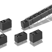
G6B-2214P-US-DC5 Omron, G6B-2214P-US-DC5 Datasheet - Page 3
G6B-2214P-US-DC5
Manufacturer Part Number
G6B-2214P-US-DC5
Description
General Purpose / Industrial Relays STD DPST-NO 5VDC
Manufacturer
Omron
Series
G6Br
Specifications of G6B-2214P-US-DC5
Coil Resistance
125 Ohms
Contact Form
DPST - NO
Coil Voltage
5 VDC
Contact Rating
5 A at 250 VAC
Contact Termination
PCB
Mounting Style
PCB
Power Consumption
300 mW
Contact Material
Silver Alloy
Coil Current
60 mA
Coil Type
Non-Latching
Relay Type
General Purpose
Coil Voltage Vdc Nom
5V
Contact Current Max
5A
Contact Voltage Ac Nom
250V
Contact Voltage Dc Nom
30V
Contact Configuration
DPST-NO
Current, Rating
5 A
Dielectric Rating
3000 VAC
Function
Power
Mounting Type
PCB
Number Of Pins
6
Power, Rating
1250⁄150 VA⁄W
Standards
UL, CSA, FCC
Termination
Through Hole
Voltage, Control
5 VDC
Voltage, Rating
380 VAC
Lead Free Status / RoHS Status
Lead free / RoHS Compliant
Lead Free Status / RoHS Status
Lead free / RoHS Compliant, Lead free / RoHS Compliant
Other names
5DC G6B-2214P-US G6B2214PUS5DC,
Available stocks
Company
Part Number
Manufacturer
Quantity
Price

Company:
Part Number:
G6B-2214P-US-DC5V
Manufacturer:
OMRON
Quantity:
12 000


G6B
■
Note:
■
Note:
Load
Rated load
Contact material
Rated carry current
Max. switching voltage
Max. switching current
Max. switching power
Failure rate (reference value)
Load
Rated load
Contact material
Rated carry current
Max. switching voltage
Max. switching current
Max. switching power
Failure rate (reference value)
Contact resistance
Operate (set) time
Release (reset) time
Min. set/reset signal width
Max. operating frequency
Insulation resistance
Dielectric strength
Vibration resistance
Shock resistance
Endurance
Ambient temperature
Ambient humidity
Weight
Contact Ratings
Characteristics
P level:
The data shown above are initial values.
Item
Item
λ
60
= 0.1 x 10
-6
/operation
Resistive load
(cosφ = 1)
5 A at 250 VAC;
5A at 30 VDC
Ag Alloy (Cd free)
5 A
380 VAC, 125 VDC
5 A
1,250 VA, 150 W
10 mA at 5 VDC
Resistive load (cosφ = 1)
8 A at 250 VAC; 8 A at 30 VDC
Ag Alloy (Cd free)
8 A
380 VAC, 125 VDC
8 A
2,000 VA, 150 W
10 mA at 5 VDC
30 mΩ max.
10 ms max. (mean value: 1-pole approx. 3 ms, 2-pole approx. 4 ms)
Single-side stable types: 10 ms max. (mean value: 1-pole approx. 1 ms, 2-pole approx. 2 ms)
Latching types:
Latching type: 15 ms min. (at 23°C)
Mechanical: 18,000 operations/hr
Electrical:
1,000 MΩ min. (at 500 VDC, at 250 VDC between set coil and reset coil)
3,000 VAC (Latching types: 2,000 VAC), 50/60 Hz for 1 min between coil and contacts
1,000 VAC, 50/60 Hz for 1 min between contacts of same polarity
250 VAC, 50/60 Hz for 1 min between set and reset coils
2,000 VAC, 50/60 Hz for 1 min between contacts of different polarity
Destruction: 10 to 55 to 10 Hz, 0.75-mm single amplitude (1.5-mm double amplitude)
Malfunction: 10 to 55 to 10 Hz, 0.75-mm single amplitude (1.5-mm double amplitude)
Destruction: 1,000 m/s
Malfunction: Single-side stable: 100 m/s
Mechanical: 50,000,000 operations min. (at 18,000 operations/hr)
Electrical:
Operating: −25°C to 70°C (with no icing)
Operating: 5% to 85%
Double-winding latching: Approx. 3.7 g
High-capacity:
Double pole:
Other:
100,000 operation min. (at 1,800 operations/hr)
1,800 operations/hr (under rated load)
SPST-NO
Inductive load
(cosφ = 0.4; L/R = 7 ms)
2 A at 250 VAC;
2 A at 30 VDC
500 VA, 60 W
2
Approx. 4.6 g
Approx. 4.5 g
Approx. 3.5 g
10 ms max. (mean value: approx. 3 ms)
SPST-NO (High-capacity)
2
; Latching: 300 m/s
Inductive load (cosφ = 0.4; L/R = 7 ms)
2 A at 250 VAC; 2 A at 30 VDC
Resistive load
(cosφ = 1)
5 A at 250 VAC;
5A at 30 VDC
1,250 VA, 150 W
SPST-NO + SPST-NC, DPST-NO, DPST-NC
2
Inductive load
(cosφ = 0.4; L/R = 7 ms)
1.5 A at 250 VAC;
1.5 A at 30 VDC
375 VA, 80 W
G6B
175