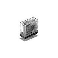
G2RL-14-DC24 Omron, G2RL-14-DC24 Datasheet - Page 5

G2RL-14-DC24
Manufacturer Part Number
G2RL-14-DC24
Description
General Purpose / Industrial Relays SPDT 24VDC Sealed Class F Gen purpose
Manufacturer
Omron
Series
G2RLr
Specifications of G2RL-14-DC24
Coil Resistance
1.44 K Ohms
Contact Form
SPDT
Coil Voltage
24 VDC
Contact Rating
12 A
Contact Termination
Solder Pin
Mounting Style
Through Hole
Power Consumption
400 mW
Contact Material
Silver Tin Oxide
Coil Current
16.7 mA
Coil Type
Non-Latching
Relay Type
General Purpose
Coil Voltage Vdc Nom
24V
Contact Current Max
12A
Contact Voltage Ac Nom
250V
Contact Voltage Dc Nom
24V
Contact Configuration
SPDT
Brand/series
G2RL Series
Current, Rating
12 A
Dielectric Rating
5000 VAC @ 1 (Min.) between Coil and Contacts
Dimensions
29 mm L x 12.7 mm W x 15.7 mm H
Function
General Purpose
Mounting Type
PCB
Number Of Pins
5
Power, Rating
3000⁄288 VA⁄W
Resistance, Coil
1440 Ohms
Resistance, Contact
100 MegOhms (Max.)
Standards
UL, CSA, VDE
Temperature, Operating
-40 to +85 °C
Termination
Through Hole
Voltage, Control
24 VDC
Voltage, Rating
440 VAC
Lead Free Status / RoHS Status
Lead free / RoHS Compliant
Lead Free Status / RoHS Status
Lead free / RoHS Compliant, Lead free / RoHS Compliant
Other names
24DC G2RL-14
Dimensions
Note: All units are in millimeters unless otherwise indicated.
G2RL-1A(-H), G2RL-1A4
G2RL-1(-H), G2RL-14
G2RL-1A-E, G2RL-1A4-E
G2RL-1-E, G2RL-14-E
G2RL-2A, G2RL-2A4
G2RL-2, G2RL-24
15.7 max.
(15.5)*
15.7 max.
(15.5)*
15.7 max.
(15.5)*
15.7 max.
(15.5)*
15.7 max.
(15.5)*
15.7 max.
(15.5)*
3.5
3.5
3.5
3.5
3.5
3.5
0.5
0.5
0.5
0.5
0.5
0.5
29 max.
(28.8)*
29 max.
(28.8)*
29 max.
(28.8)*
29 max.
(28.8)*
29 max.
(28.8)*
0.5
0.5
29 max.
(28.8)*
0.5
0.5
0.5
0.5
0.5
0.5
0.5
0.5
0.5
0.5
0.5
0.5
0.5
12.7 max.
(12.5)*
12.7 max.
(12.5)*
12.7 max.
(12.5)*
12.7 max.
(12.5)*
12.7 max.
(12.5)*
12.7 max.
(12.5)*
0.8
0.8
0.8
0.8
0.8
0.8
* Indicates average dimensions.
* Indicates average dimensions.
* Indicates average dimensions.
Terminal Arrangement/
Internal Connection
(Bottom View)
Terminal Arrangement/
Internal Connection
(Bottom View)
Terminal Arrangement/
Internal Connection
(Bottom View)
* Indicates average dimensions.
Terminal Arrangement/
Internal Connection
(Bottom View)
* Indicates average dimensions.
* Indicates average dimensions.
Terminal Arrangement/
Internal Connection
(Bottom View)
Terminal Arrangement/
Internal Connection
(Bottom View)
1
5
8
1
1
8
1
8
1
8
1
5
7
2
2
7
2
4
3
6
3
6
3
6
6
3
3
4
4
5
5
4
4
5
4
5
3
(2.3)
(2.3)
(2.3)
7.5
7.5
7.5
(2.3)
(2.3)
7.5
7.5
(2.3)
7.5
Mounting Holes
(Bottom View)
Mounting Holes
(Bottom View)
Mounting Holes
(Bottom View)
Mounting Holes
(Bottom View)
Mounting Holes
(Bottom View)
Mounting Holes
(Bottom View)
PCB Relay
20
20
20
20
20
20
5
5
3.5 3.5
5
5
3.5
5
5
Eight, 1.3±0.1 dia.
holes
Eight, 1.3±0.1 dia.
holes
G2RL
Five, 1.3±0.1 dia.
holes
Four, 1.3±0.1 dia.
holes
(2.5)
Six, 1.3±0.1 dia.
holes
Six, 1.3±0.1 dia.
holes
(2.5)
(2.5)
(2.5)
(2.5)
(2.5)
207


