GRF172-12 TELEDYNE, GRF172-12 Datasheet
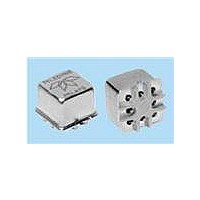
RF (Radio Frequency) Relays 12V DC-6GHz .15W

GRF172-12

Manufacturer Part Number
GRF172-12
Description
RF (Radio Frequency) Relays 12V DC-6GHz .15W
Manufacturer
TELEDYNE
Series
GRF172r
Datasheets

Specifications of GRF172-12

Coil Current
0.15 W
Frequency
6 GHz
Contact Form
2 Form C (DPDT)
Coil Voltage
12 VDC
Power Consumption
360 mW
Termination Style
SMD/SMT
Coil Voltage Vdc Nom
12V
Contact Current Max
1A
Contact Voltage Dc Nom
28V
Coil Resistance
400ohm
Coil Type
DC Coil
Relay Mounting
PC Board
External Width
9.53mm
External Depth
9.53mm
Brand/series
GRF172 Series
Current, Rating
1 A
Function
Frequency (RF)
Mounting Type
PCB
Number Of Pins
8
Relay Type
Electro Mechanical
Termination
Surface Mount
Voltage, Control
12 VDC
Voltage, Rating
28 VDC
Contact Configuration
DPDT
External Height
8.38mm
Rohs Compliant
Yes
Lead Free Status / RoHS Status
Lead free / RoHS Compliant
Lead Free Status / RoHS Status
Lead free / RoHS Compliant, Lead free / RoHS Compliant
©2004 TELEDYNE RELAYS
Temperature
(Ambient)
Vibration
(General Note 1)
Shock
(General Note 1)
Enclosure
Weight
INTERNAL CONSTRUCTION
PHYSICAL SPECIFICATIONS
ENVIRONMENTAL AND
Storage
Operating –55°C to +85°C
DESIGNATION
GRF172D
GRF172
SERIES
–65°C to +125°C
10 g’s to 500 Hz
30 g’s,
6 msec, half-sine
Hermetically sealed
0.09 oz. (2.55g) max.
SPECIFICATIONS ARE SUBJECT TO CHANGE WITHOUT NOTICE
Surface mount, RF Centigrid
2.5 GHz RF RELAYS
SURFACE MOUNT,
DESCRIPTION
The GRF172 surface-mount Centigrid
sealed, armature relay for 2.5 GHz RF applications. Its low profile height
(.330") and .100" grid spaced terminals make it an ideal choice where extreme
packaging density and/or close PC board spacing are required.
The GRF172 features a unique ground shield that isolates and shields each
lead to ensure excellent contact-to-contact and pole-to-pole isolation. This
ground shield provides a ground interface that results in improved high-
frequency performance as well as parametric repeatability. The GRF172
extends performance advantages over similar RF devices that simply offer
formed leads for surface mounting.
Unique construction features and manufacturing techniques provide overall
high reliability and excellent resistance to environmental extremes:
• All welded construction.
• Unique uni-frame design providing high magnetic efficiency and mechanical
• High force/mass ratios for resistance to shock and vibration.
• Advanced cleaning techniques provide maximum assurance of internal
• Precious metal alloy contact material with gold plating assures excellent
The Series GRF172D has an internal discrete silicon diode for coil transient
suppression.
Applications
communications, attenuators, and automatic test equipment.
rigidity.
cleanliness.
high current and dry circuit switching capabilities.
www.teledynerelays.com
CENTIGRID
DPDT
include
®
®
relay
relay with coil transient suppresson diode
RELAY TYPE
telecommunications,
®
®
relay is an ultraminiature, hermetically
test
instruments,
GRF172
SERIES
GRF172 Page 1
GRF172/0204/Q1
mobile

Related parts for GRF172-12

GRF172-12 Summary of contents

Page 1

... Advanced cleaning techniques provide maximum assurance of internal cleanliness. • Precious metal alloy contact material with gold plating assures excellent high current and dry circuit switching capabilities. The Series GRF172D has an internal discrete silicon diode for coil transient suppression. Applications include telecommunications, communications, attenuators, and automatic test equipment ...

Page 2

... GRF172 Time Response (RF Note 6) 1.1 0.9 90% 0.7 37ps reference 0.5 89.25ps propagation delay time 0.3 58.5ps pulse rise time 10% 0.1 -0.1 -100 0 100 200 300 400 ...

Page 3

... SERIES GRF172 TYPICAL RF INSERTION LOSS REPEATABILITY CHARACTERISTICS REPEATABILITY CHARACTERISTICS GRF172 RELAYS Normally Closed 100% 90% 80% 70% 60% 50% 0 0.02 0.04 0.06 0.08 0.1 Repeatability (dB) RF INSERTION LOSS REPEATABILITY NOTES 1. Test conditions: a. Fixture: .031" copper clad, reinforced PTFE, RT/duroid registered trademark of Rogers Corporation.) b. Test performed at room ambient temperature. c. Contact signal level: – ...

Page 4

... TYP (2.54) NOTES: 1. DIMENSIONS ARE IN INCHES. METRIC EQUIVALENTS IN MILLIMETERS ARE SHOWN UNLESS OTHERWISE SPECIFIED, TOLERANCES ON DIMENSIONS ARE ±.010 INCH (0.025 mm). 3. FOR OPTIMAL RF PERFORMANCE, SOLDER BOTTOM OF GROUND SHIELD TO PCB RF GROUND PLANE. www.teledynerelays.com GRF172-12 GRF172D-12 5.0 12.0 5.8 16.0 64 400 3 ...

Page 5

... Unless otherwise specifi ed, tolerance is ± .010 (.25). 5. Add 10 mΩ to the contact resistance show in the datasheet. 6. Add 0.01 oz. (0. the weight of the relay assembly shown in the datasheet. © 2008 Teledyne Relays Appendix A: Spacer Pads Height For use with the following: ...

Page 6

... MAX .014 [0.36] (REF) .370 [9.4] MIN ♦ +44 (0) 1236 453124 • www.teledyne-europe.com For use with the following: ER411T, J411T, ER412, ER412D ER412DD, J412, J412D, J412DD ER412T, J412T 712, 712D, 712TN ER431T, J431T, ER432, ER432D ER432DD, J432, J432D, J432DD ER432T, J432T ...

Page 7

... Centigrid® Relays: RF180, ER116C, 122C, ER136C Indicates ground pin position Indicates glass insulated lead position Indicates ground pin or lead position depending on relay type © 2008 Teledyne Relays "Z" POSITION "X" POSITION "Y" POSITION TO-5 Relays: ER411, ER431, RF311, RF331 " ...

Related keywords