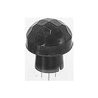
AMN14112 Panasonic, AMN14112 Datasheet - Page 8

AMN14112
Manufacturer Part Number
AMN14112
Description
Industrial Motion & Position Sensors DIGITAL 5VDC WHITE 10 METER DETECTION
Manufacturer
Panasonic
Datasheet
1.AMN14112.pdf
(8 pages)
Specifications of AMN14112
Voltage Rating
3 VDC to 6 VDC
Temperature Range
- 20 C to + 60 C
Maximum Operating Temperature
+ 60 C
Maximum Voltage
6 VDC
Minimum Operating Temperature
- 20 C
Mounting Style
Through Hole
Product
Passive Infrared Sensors
Sensing Distance
20 cm
Supply Current
170 uA
Supply Voltage (max)
6 V
Supply Voltage (min)
3 V
Output Type
Digital
Lead Free Status / RoHS Status
Lead free / RoHS Compliant
Other names
PEWA
Available stocks
Company
Part Number
Manufacturer
Quantity
Price
Company:
Part Number:
AMN14112
Manufacturer:
MAXIM
Quantity:
144
MP Motion Sensor (AMN1,2,4)
3. Spot detection type
Notes: 1. As for panel mounting hole, tapering or making a large size hole should be
NOTES
1. Checkpoints relating to principle of
operation
MP motion sensors are passive infrared
sensors which detect changes in the
infrared rays. They may fail to detect
successfully if a heat source other than a
human being is detected or if there are
no temperature changes in or movement
of a heat source. Care must generally be
taken in the following cases. The perfor-
mance and reliability of the sensors must
be checked out under conditions of actu-
al use.
<1> Cases where a heat source other
1) When a small animal enters the detec-
tion range.
2) When the sensor is directly exposed
to sunlight, a vehicle’s headlights, an
incandescent light or some other source
of far infrared rays.
3) When the temperature inside the
detection range has changed suddenly
due to the entry of cold or warm air from
an air-conditioning or heating unit, water
vapor from a humidifier, etc.
<2> Cases where it is difficult to
detect the heat source
1) When an object made of glass, acrylic
or other subject which far infrared rays
have difficulty passing through is located
between the sensor and what is to be
detected.
18
Molding gate
0.45
.018
±0.05
±.002
Vdd
than a human being is detected.
2. The height dimension does not include the remaining molding gate.
dia.
dia.
OUT
done.
.350 dia.
8.9 dia.
.433
11
GND
Note 2 )
P.C.D. 5.08
15.1
.594
4.5
.177
.200
±.008
±0.2
dia.
dia.
Recommended PC board pattern
(BOTTOM VIEW)
.370
9.4
+0.2
-0
+.008
-0
dia.
dia.
2) When the heat source inside the
detection range hardly moves or when it
moves at high speed; for details on the
movement speed, refer to the section on
the performance ratings.
2. When the detection area becomes
larger
When the difference between the ambi-
ent temperature and body temperature is
large (more than 20°C 68°F), detection
may occur in isolated areas outside the
specified detection range.
3. Other handling cautions
1) Be careful not to allow dust or dirt to
accumulate on the lens as this will
adversely affect the detection sensitivity.
2) The lens is made of a soft material
(polyethylene).
Avoid applying a load or impact since
this will deform or scratch the lens, mak-
ing proper operation impossible and
causing a deterioration in its perfor-
mance.
3) The sensor may be damaged if it is
exposed to static with a voltage exceed-
ing ±200V. Therefore, do not touch its
terminals directly, and exercise adequate
care in the handling of the sensor.
4) When the leads are to be soldered,
solder them by hand for less than 3 sec-
onds at a temperature of less than 350°C
662°F
Avoid using a solder bath since this will
causing a deterioration in the sensor’s
performance.
Note 1 )
at the tip of the soldering iron.
Molding
gate
0.45
.018
4. 10m detection type
±0.05
±.002
Vdd
OUT
dia.
dia.
17.4 dia.
.685 dia.
17.0 dia.
.670 dia.
.433 dia.
11 dia.
GND
P.C.D. 5.08
8.6
.339
Note 3 )
.200
18.53
.730
4.5
.177
±.008
±0.2
dia.
dia.
Notes:
1. In order to ensure proper detection, install it with the lens
2. As for panel mounting hole, tapering or making a large size
3. The height dimension does not include the remaining mold-
5) Do not attempt to clean the sensor.
Cleaning fluid may enter inside the lens
area causing a deterioration in perfor-
mance.
6) When using the sensors with cables, it
is recommended that cables which are
shielded and as short as possible be
used in order to safeguard against the
effects of noise.
For the general precautions, refer to the
Notes for Motion Sensors on page 27.
exposed at least 5.6mm .220inch.
hole should be done.
ing gate.
Recommended PC board pattern
mm
Note 1 )
inch
(BOTTOM VIEW)
General tolerance ±0.5
Sensing area
17.9
.705
+.008
-0
+0.2
-0
dia.
dia.
Note 2 )
12.9
.508
±.020


