TL-W3MC2 Omron, TL-W3MC2 Datasheet - Page 2
TL-W3MC2
Manufacturer Part Number
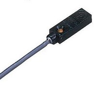
TL-W3MC2
Description
Proximity Sensors PROX RCT PK NPN NC 3MM
Manufacturer
Omron
Type
Inductive Proximity Sensorr
Datasheet
1.TL-W3MC2.pdf
(9 pages)
Specifications of TL-W3MC2
Maximum Operating Temperature
+ 70 C
Supply Voltage
10 V to 30 V
Supply Current
15 mA
Operating Supply Voltage
10 V to 30 V
Mounting Style
Cable
Minimum Operating Temperature
- 25 C
Maximum Output Current
100 mA
Features
NC
Sensing Distance
3 mm
Sensor Input
Inductive
Sensing Range
3mm
Supply Voltage Range Dc
10V To 30V
Lead Free Status / RoHS Status
Lead free / RoHS Compliant
Lead Free Status / RoHS Status
Lead free / RoHS Compliant, Lead free / RoHS Compliant
Available stocks
Company
Part Number
Manufacturer
Quantity
Price

Company:
Part Number:
TL-W3MC2 2M
Manufacturer:
OMRON
Quantity:
500
Company:
Part Number:
TL-W3MC2-R 2M
Manufacturer:
OMRON
Quantity:
500
Company:
Part Number:
TL-W3MC25 2M
Manufacturer:
OMRON
Quantity:
500


Ratings and Specifications
DC 2-Wire Models
*1. The response frequency is an average value.
*2. For environments that require oil resistance, the upper limit of the ambient operating temperature range is 40°C.
Item
Sensing distance
Set distance
Differential travel
Detectable object
Standard sensing object
Response frequency *1
Power supply voltage
(operating voltage range)
Leakage current
Con-
trol
output
Indicators
Operation mode (with sensing
object approaching)
Protection circuits
Ambient temperature range
Ambient humidity range
Temperature influence
Voltage influence
Insulation resistance
Dielectric strength
Vibration resistance
Shock resistance
Degree of protection
Connection method
Weight (packed state)
Materials
Accessories
Measurement conditions are as follows: standard sensing object, a distance of twice the standard sensing object, and a set distance of half the sensing distance.
Load current
Residual voltage
Case
Sensing surface
Model
5 mm ±10%
0 to 4 mm
10% max. of sensing distance
Ferrous metal (The sensing distance decreases with non-ferrous metal. Refer to Engineering Data on page
5.)
Iron, 18 × 18 × 1 mm
500 Hz
12 to 24 VDC (10 to 30 VDC), ripple (p-p): 10% max.
0.8 mA max.
3 to 100 mA
3.3 V max. (under load current of 100 mA with cable length of 2 m)
D1 Models: Operation indicator (red), Setting indicator (green)
D2 Models: Operation indicator (red)
D1 Models: NO
D2 Models: NC
Load short-circuit protection, Surge suppressor
Operating/Storage: −25 to 70°C (with no icing or condensation) *2
Operating/Storage: 35% to 95% (with no condensation)
±10% max. of sensing distance at 23°C in the temperature range of −25 to 70°C
±2.5% max. of sensing distance at rated voltage in the rated voltage ±15% range
50 MΩ min. (at 500 VDC) between current-carrying parts and case
1,000 VAC for 1 min between current-carrying parts and case
Destruction: 10 to 55 Hz, 1.5-mm double amplitude for 2 hours each in X, Y, and Z directions
Destruction: 500 m/s
IEC 60529 IP67, in-house standards: oil-resistant *2
Pre-wired Models (Standard cable length: 2 m)
Approx. 45 g
Heat-resistant ABS
Instruction manual
Refer to the timing charts under I/O Circuit Diagrams on page 6 for details.
2
3 times each in X, Y, and Z directions
TL-W5MD@
TL-W
2
Related parts for TL-W3MC2
Image
Part Number
Description
Manufacturer
Datasheet
Request
R

Part Number:
Description:
Proximity Sensors TL-W3MB1 W/ ROBOTIC CABLE 2M
Manufacturer:
Omron
Datasheet:

Part Number:
Description:
Proximity Sensors TL-M2ME1 W/ 5 METER CABLE
Manufacturer:
Omron
Datasheet:

Part Number:
Description:
Proximity Sensors MINI FLAT PROX 2MM NPN NO SHLD
Manufacturer:
Omron
Datasheet:
Part Number:
Description:
Proximity Sensors Miniature Inductive 3-Wire DC PNP-NO
Manufacturer:
Omron
Datasheet:
Part Number:
Description:
Proximity Sensors INDUCTIVE NPN-NO
Manufacturer:
Omron
Datasheet:
Part Number:
Description:
Proximity Sensors INDUCTIVE PNP-NO
Manufacturer:
Omron
Datasheet:
Part Number:
Description:
Proximity Sensors MINI FLAT PROX
Manufacturer:
Omron
Datasheet:
Part Number:
Description:
Proximity Sensors INDUCTIVE NPN-NO
Manufacturer:
Omron
Datasheet:

Part Number:
Description:
Inductive Proximity Sensor
Manufacturer:
Omron
Datasheet:

Part Number:
Description:
BLOCK PRX,10MM,NPN,NC,UNSH
Manufacturer:
Omron
Datasheet:
Part Number:
Description:
AC,BLOCK PRX,5MM,NO,UNSH
Manufacturer:
Omron
Datasheet:
Part Number:
Description:
AC,FLAT PRX,2MM,NO,SHLD
Manufacturer:
Omron
Datasheet:
Part Number:
Description:
FLAT PROXIMITY
Manufacturer:
Omron
Datasheet:

Part Number:
Description:
MINI FLAT PROX
Manufacturer:
Omron
Datasheet: