H7CX-A114D1-N-DC12-24/AC24 Omron, H7CX-A114D1-N-DC12-24/AC24 Datasheet - Page 47
H7CX-A114D1-N-DC12-24/AC24
Manufacturer Part Number
H7CX-A114D1-N-DC12-24/AC24
Description
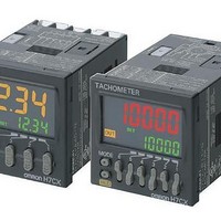
Tachometers 11-pin SPDT 4 Digits 12-24VDC/VAC24
Manufacturer
Omron
Type
1 Stage and Total Preset Counterr
Datasheet
1.H7CX-A-N_AC100-240.pdf
(56 pages)
Specifications of H7CX-A114D1-N-DC12-24/AC24
Frequency Response
50 Hz
Product
Panel Mount Tachometer
Voltage
12 VDC to 24 VDC
Display Type
4 Digit
Accuracy
+/- 0.1 %
Lead Free Status / RoHS Status
Lead free / RoHS Compliant
Other names
DC1224/AC24 H7CXA114D1N H7CXA114D1NDC1224/AC24


Operation in Run Mode
*1 Peak/bottom hold enabled
H7CX-R11W@-N
H7CX-R11@-N
Output Mode: HI or LO
• Set each digit using the individual U Keys.
Displayed for Models Other Than “-W” Models
Peak hold value
Bottom hold value
*1
Measurement value
Measurement value
Comparison value
Measurement value 1
Comparison value 1
Measurement value 2
Comparison value 2
Output Mode: HI-LO or AREA
Displayed for “-W” Models
Peak hold value 1
Bottom hold value 1
Peak hold value 2
Bottom hold value 2
*1
Measurement value
Measurement value
Comparison value 1
Measurement value
Comparison value 2
• Peak/bottom hold value
• Peak/bottom hold value 2
The peak (maximum) and bottom (minimum)
Peaks (maximums) 1 and 2 and bottoms
values are displayed after counting starts.
(minimums) 1 and 2 are displayed after counting
starts.
Note: The held values will be initialized when the
• Measurement Value
• Comparison Value, Comparison Value 1, and
Displays the currently measured value.
Comparison Value 2
and comparison value 2.
comparison value, comparison value 1, and
comparison value 2 and an output is made
according to the selected output mode.
Set the comparison value, comparison value 1,
The measurement value is compared to
Hold Key or reset 1 input is turned OFF
while peak/bottom hold values 1 and 2 are
being displayed.(The reset 2 input
operates in the same way if the input
mode is set to 2-input mode.)
H7CX-R@-N
47