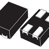
STLM20DD9F STMicroelectronics, STLM20DD9F Datasheet - Page 9

STLM20DD9F
Manufacturer Part Number
STLM20DD9F
Description
Board Mount Temperature Sensors 2.4V Analog
Manufacturer
STMicroelectronics
Datasheet
1.STLM20W87F.pdf
(19 pages)
Specifications of STLM20DD9F
Full Temp Accuracy
+/- 1.5 C
Package / Case
UDFN-4
Supply Voltage (max)
6.5 V
Supply Voltage (min)
- 0.2 V
Gain
- 11.77 mV / C
Maximum Operating Temperature
+ 85 C
Minimum Operating Temperature
- 40 C
Output Type
Analog
Supply Current
8 uA
Ic Output Type
Voltage
Sensing Accuracy Range
± 1.5°C
Temperature Sensing Range
-40°C To +85°C
Supply Voltage Range
2.4V To 5.5V
Sensor Case Style
UDFN
No. Of Pins
4
Rohs Compliant
Yes
Lead Free Status / RoHS Status
Lead free / RoHS Compliant
Available stocks
Company
Part Number
Manufacturer
Quantity
Price
Company:
Part Number:
STLM20DD9F
Manufacturer:
NVIDIA
Quantity:
81
Part Number:
STLM20DD9F
Manufacturer:
ST
Quantity:
20 000
STLM20
4
Table 6.
1. Valid for ambient operating temperature: T
2. T
3. Accuracy is defined as the error between the measured and calculated output voltage at specified conditions of voltage,
4. Positive load currents flow out of the device (sourcing) and can typically be 16 µA. For negative load currents (sinking), the
5. Over the supply range of 2.4 to 5.5 V.
6. Measured at constant junction temperature, with pulse testing and low duty cycle. Output changes due to heating may be
RegI1
RegI2
T
RegL
Sym
V
ΔI
I
V
C
Z
current, and temperature.
device can sink less than 1 µA.
calculated by multiplying internal dissipation by thermal resistance.
I
SD
CC
Q
V
O
O
J
Q
O
= T
A
Supply voltage
Output voltage
Second order parabolic equation
Temperature to voltage error
V
(–1.15 x 10
Quiescent current
Sensor gain (temperature sensitivity
or average slope),
V
Non-linearity
Change of quiescent current
Temperature coefficient of quiescent
current
Shutdown current
Output impedance
Load regulation
Line regulation
= 25 °C, unless otherwise noted under test condition.
O
O
= (–3.88 x 10
= –11.77 mV/°C * T + 1.860 V
DC and AC characteristics
This section summarizes the DC and AC characteristics of the device. The parameters in
the DC and AC characteristics table that follows are derived from tests performed under the
test conditions. Designers should check that the operating conditions in their circuit match
the operating conditions when relying on the quoted parameters.
DC and AC characteristics
–2
Description
* T) + 1.8639 V
(6)
–6
* T
2
) +
(3)
A
= –55 to 130 °C or T
Doc ID 12495 Rev 13
T
A
T
T
0 µA ≤ I
–30 °C ≤ T
–20 °C ≤ T
A
A
2.4 V ≤ V
2.4 V ≤ V
2.4 V ≤ V
5.0 V ≤ V
T
T
= –55 °C to 130 °C or
Test condition
A
A
= –30 °C to 130 °C
= 125 °C to 130 °C
–40 °C to 85 °C
= 80 °C to 85 °C
= 25 °C to 30 °C
T
T
V
A
A
T
T
CC
A
A
L
= –40 °C
= –55 °C
A
= 0 °C
= 0 °C
≤ 16 µA
≤ 0.8 V
= –40 to 85 °C; V
CC
CC
CC
CC
A
A
≤ 100 °C
≤ 80 °C
≤ 5.5 V
≤ 5.5 V
≤ 5.0 V
≤ 5.5 V
(4)(5)
(1)
CC
–11.4
Min
= 2.7 V (except where noted).
2.4
2.7
DC and AC characteristics
1.8639
–11.77
Typ
±1.00
±0.75
±0.5
±0.4
0.02
–11
4.8
0.7
(2)
–12.2
Max
±2.5
±2.1
±1.5
±1.9
±2.3
±2.5
–2.5
160
5.5
5.5
3.3
11
8
mV/°C
nA/°C
mV/V
Unit
mV
mV
µA
µA
µA
°C
°C
°C
°C
°C
°C
%
V
Ω
V
V
9/19


