MM8430-2610RA1 Murata Electronics North America, MM8430-2610RA1 Datasheet - Page 15
MM8430-2610RA1
Manufacturer Part Number
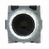
MM8430-2610RA1
Description
CONN MW COAXIAL WITH SWITCH SMD
Manufacturer
Murata Electronics North America
Series
8430r
Datasheet
1.MM8430-2610RA1.pdf
(39 pages)
Specifications of MM8430-2610RA1
Connector Style
SWD
Connector Type
Jack, Female Sockets
Contact Termination
Solder
Impedance
50 Ohm
Mounting Type
Surface Mount
Fastening Type
Push-Pull
Frequency - Max
6GHz
Features
Internal Switch
Frequency-max
6GHz
Lead Free Status / RoHS Status
Lead free / RoHS Compliant
Color
-
Cable Group
-
Other names
490-4980-2
Available stocks
Company
Part Number
Manufacturer
Quantity
Price
Company:

Part Number:
MM8430-2610RA1
Manufacturer:
MURATA
Quantity:
1 000
Company:
Part Number:
MM8430-2610RA1
Manufacturer:
COPAL
Quantity:
429
Part Number:
MM8430-2610RA1
Manufacturer:
MURATA/村田
Quantity:
20 000


!Note
• This PDF catalog is downloaded from the website of Murata Manufacturing co., ltd. Therefore, it’s specifications are subject to change or our products in it may be discontinued without advance notice. Please check with our
• This PDF catalog has only typical specifications because there is no space for detailed specifications. Therefore, please approve our product specifications or transact the approval sheet for product specifications before ordering.
sales representatives or product engineers before ordering.
!Note
1. Automatic Measurement Probe (MM126036)
2. L Type Probe with Locking Function
3. Usage Condition
4. Handling
(1) Do not apply electrical voltage greater than specified
(2) Confirm that product performance is not influenced
(MXHS83QE3000, MXHS83QH3000)
Notice (Handling)
Automatic measurement probe (MM126036) should be
used under conditions in Fig. 1 for good connection
without any damages.
The engagement strokes from the flange to the tip of
probe is 18.28mm to 19.78mm with vertical (0 2 )
direction.
Avoid pulling cable when probe is locked into connector.
Avoid twisting probe or cable when engaging or
disengaging from connector.
Mechanical stress:
The stress to the connector should be limited as figure
shown right.
(1) Stress to the housing.
(2) Stress to the outer sleeve.
(3) Cable pull strength.
Avoid excessive stress when handling and transporting
printed circuit board after connector and/or assembly
has been secured to PCB.
Continued from the preceding page.
• Please read rating and !CAUTION (for storage, operating, rating, soldering, mounting and handling) in this catalog to prevent smoking and/or burning, etc.
• This catalog has only typical specifications because there is no space for detailed specifications. Therefore, please approve our product specifications or transact the approval sheet for product specifications before ordering.
in the catalog. It might cause degradation or
destruction of the product. Even if it endures during a
short time, long time qualification is not guaranteed.
with any other components or materials which
directly contact products.
Stress A and B: 0.5N max.
Stress C: 0.6N max.
Stress D: 0.6N max.
Stress E: 0.5N max.
Fig. 1
A
Insertion the Automatic Measurement Probe
(MM126036) in Receptacle (MM8430-2610)
Mechanical stress after engagement
MM8430-2610
PCB
B
1.5 (Using Range)
C
D
0
Notice
2
E
O30E.pdf
13
07.9.3
2
Related parts for MM8430-2610RA1
Image
Part Number
Description
Manufacturer
Datasheet
Request
R

Part Number:
Description:
CONN MW COAXIAL WITH SWITCH SMD
Manufacturer:
Murata Electronics North America
Datasheet:

Part Number:
Description:
RF Connectors COAXIAL CONNECTOR MS3
Manufacturer:
Murata
Datasheet:

Part Number:
Description:
RF Connectors MS3
Manufacturer:
Murata
Datasheet:
Part Number:
Description:
RF Connectors SMD SWITCH CONNECTOR
Manufacturer:
Murata
Datasheet:
Part Number:
Description:
RF Connectors MICROWAVE CONNECTOR WITH SWTCH HI TEMP
Manufacturer:
Murata
Datasheet:

Part Number:
Description:
BUZZER PIEZO 25VP-P SMD
Manufacturer:
Murata Electronics North America

Part Number:
Description:
CAP 4-ARRAY 680PF 100V X7R 1206
Manufacturer:
Murata Electronics North America
Datasheet:
Part Number:
Description:
CAP 4-ARRAY 1000PF 100V X7R 1206
Manufacturer:
Murata Electronics North America
Datasheet:
Part Number:
Description:
CAP 4-ARRAY 1800PF 100V X7R 1206
Manufacturer:
Murata Electronics North America
Datasheet:
Part Number:
Description:
CAP 4-ARRAY 68000PF 16V X7R 1206
Manufacturer:
Murata Electronics North America
Datasheet:

Part Number:
Description:
CAP CER 1000PF 50V 10% X7R 0402
Manufacturer:
Murata Electronics North America
Datasheet:

Part Number:
Description:
CAP 5.5-25PF 2.5X3.2MM SMD
Manufacturer:
Murata Electronics North America
Datasheet:

Part Number:
Description:
CAP 4.5-20PF 2.5X3.2MM SMD
Manufacturer:
Murata Electronics North America
Datasheet:

Part Number:
Description:
CAP 5.0-20PF 3.2X4.5MM SMD RED
Manufacturer:
Murata Electronics North America
Datasheet:

Part Number:
Description:
CAP 2.0-6.0PF 3.2X4.5MM SMD BLU
Manufacturer:
Murata Electronics North America
Datasheet: