531-40047-3 AMPHENOL RF, 531-40047-3 Datasheet - Page 8
531-40047-3
Manufacturer Part Number
531-40047-3
Description
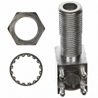
CONN F SOCKET R/A W/HARDWARE PCB
Manufacturer
AMPHENOL RF
Series
F Typer
Datasheet
1.531-40047-3.pdf
(8 pages)
Specifications of 531-40047-3
Connector Style
F Type
Connector Type
Receptacle, Female Sockets
Contact Termination
Solder
Impedance
75 Ohm
Mounting Type
Through Hole, Bulkhead, Right Angle
Fastening Type
Threaded
Frequency - Max
1GHz
Frequency-max
1GHz
Body Style
Right Angle Jack
Coaxial Termination
Solder
Contact Material
Beryllium Copper
Contact Plating
Tin
Connector Mounting
PCB
Lead Free Status / RoHS Status
Lead free / RoHS Compliant
Features
-
Color
-
Cable Group
-
Lead Free Status / RoHS Status
Lead free / RoHS Compliant, Lead free / RoHS Compliant
Other names
ARF1715


Type F Connectors
SCTE Type F Specifications
IPS-SP-400
Recommended “F” Jack (Port)
IPS-SP-401
Recommended “F” Plug
*many Amphenol Type F connectors comply to the above specifications.
Amphenol Corporation Tel: 800-627-7100
Description
Description
Cable center conductor diameter
Nut outer diameter
Nut threaded length
Mandrel face depth to nut leading edge
Center conductor to mandrel face length
Mandrel face outer diameter
Nut to sealing sleeve interface length
Maximum envelope dimension
Chamfer break
Face opening inner diameter
Face outer diameter
Base outer diameter
Center conductor contact to face length
Port threaded length
Center contact depth
Sealing surface to face length
Center conductor guide inner diameter
Chamfer break
J X 45 chamfer
Ø
DIM
DIM
A
B
C
D
G
H
A
B
C
D
G
H
E
F
J
E
F
J
Ø
H
C
4
Ø
4.32
7.11
9.40
8.26
9.65
12.07
0.56
10.41
4.45
6.35
7.11
1.78
min
min
__
__
0.25
B
__
__
__
8
mm
mm
5
3/8-32 UNEF-2B
3
Ø
6.10
8.00
11.05
5.08
8.89
13.21
1.73
0.76
F
1.07
11.05
6.10
9.53
__
4.45
12.90
0.25
max
max
__
__
6
5
63
7
.170
.280
.370
.325
.380
.475
.022
.410
.175
.250
.280
.070
min
A
min
__
__
.010
__
__
__
ØA
in
in
G
252
.240
.315
.435
.200
.350
.520
.068
.030
.042
.435
.240
.375
.175
.508
.010
max
max
J X 45 chamfer
__
__
__
F
4
E
8
D
G
Notes
Notes
E
6
6
8
2
6
4
8
C
D
2
Ø
H
.004
2
.004
1
Ø
NOTES:
1. Dielectric must not protrude beyond reference plane
2. Reference plane after installation on standard port
3. No casting lines permitted
4. Thread relief not to exceed 1 full thread
5. Finish required for port seal ring
6. Dimension to point of positive contact of terminal
7. ANSI specification B1.1 (major dia 0.368/0.374)
8. Limit of clearance for maximum center conductor
9. Recommended center conductor 0.0513 in
NOTES:
1. Dielectric must not protrude beyond reference plane
2. Minimum 4 full threads
3. Reference plane after installation on standard port,
4. Maximum envelope dimension
5. Maximum 1 thread lead-in
6. Minimum diameter of reference plane
7. ANSI specification B1.1
8. Radius optional
9. Connectors must withstand a minimum torque of
A
3/8-32 UNEF 2A
after installation
tightened to 30 inch lbs and removed
maximum
tightened to 30 inch pounds and removed
60 inch pounds without damage per IPS-TP-400
7
3
Ø
B
1
Amphenol
www.amphenolrf.com
®
Related parts for 531-40047-3
Image
Part Number
Description
Manufacturer
Datasheet
Request
R

Part Number:
Description:
RF Connectors F-CONN F/F ADAPTER
Manufacturer:
Amphenol
Datasheet:

Part Number:
Description:
RF Connectors G VT JCK PCB
Manufacturer:
Amphenol
Datasheet:

Part Number:
Description:
RF Connectors G PLUG FOR RG-179 CABLE
Manufacturer:
Amphenol
Datasheet:

Part Number:
Description:
RF Connectors PC BOARD CONNECTOR
Manufacturer:
Amphenol
Datasheet:


Part Number:
Description:
CONN MCX JACK STR 50 OHM SMD
Manufacturer:
AMPHENOL RF
Datasheet:

Part Number:
Description:
CONN BNC JACK R/A 75 OHM PCB
Manufacturer:
AMPHENOL RF
Datasheet: