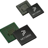
MC13892VK Freescale Semiconductor, MC13892VK Datasheet - Page 106

MC13892VK
Manufacturer Part Number
MC13892VK
Description
IC PMU I.MX51/37/35/27 139MAPBGA
Manufacturer
Freescale Semiconductor
Datasheets
1.MC13892AJVLR2.pdf
(156 pages)
2.MC13892AJVLR2.pdf
(2 pages)
3.MC13892AJVLR2.pdf
(16 pages)
Specifications of MC13892VK
Applications
Battery Management, Display (LED Drivers), Handheld/Mobile Devices, Power Supply
Operating Temperature
-40°C ~ 85°C
Mounting Type
Surface Mount
Package / Case
*
Output Current
65 mA
Output Voltage
1.5 V
Lead Free Status / RoHS Status
Lead free / RoHS Compliant
Current - Supply
-
Voltage - Supply
-
Lead Free Status / Rohs Status
Lead free / RoHS Compliant
Available stocks
Company
Part Number
Manufacturer
Quantity
Price
Company:
Part Number:
MC13892VK
Manufacturer:
FREESCALE
Quantity:
2 248
Company:
Part Number:
MC13892VK
Manufacturer:
Freescale Semiconductor
Quantity:
10 000
Company:
Part Number:
MC13892VKR2
Manufacturer:
Freescale Semiconductor
Quantity:
10 000
FUNCTIONAL DEVICE OPERATION
ADC SUBSYSTEM
TOUCH SCREEN INTERFACE
X plate is connected to TSX1 and TSX2 while the Y plate is connected to TSY1 and TSY2. A local supply TSREF will serve as
a reference. Several readout possibilities are offered.
for touch screen readings as well as for general purpose reading on the same inputs.
Table 95. Touch Screen Operating Mode
mapped on ADC channels 4, 5, 6, and 7.
connected to ground (TSY1). When the two plates make contact both will be at a low potential. This will generate a pen interrupt
to the processor. This detection does not make use of the ADC core or the TSREF regulator, so both can remain disabled.
on the Y-plate through TSY1. The Y coordinate is determined by applying TSREF between TSY1 and TSY2, while reading the
TSX1 pin.
terminal TSX2, which is grounded. The voltage difference between the two remaining terminals TSY2 and TSX1 is measured by
the ADC, and equals the voltage across the contact resistance. Measuring the contact resistance helps in determining if the touch
screen is touched with a finger or stylus.
conversions via the ATO and ATOX settings, trigger the ADC via one of the trigger sources, wait for an interrupt indicating the
conversion is done, and then read out the data. In order to reduce the interrupt rate and to allow for easier noise rejection, the
touch screen readings are repeated in the readout sequence.
the change in touch screen plate polarity and will read out as '0'.
106
13892
TSMOD2
The touch screen interface provides all circuitry required for the readout of a 4-wire resistive touch screen. The touch screen
In order to use the ADC inputs and properly convert and readout the values, the bit ADSEL should be set to a 1. This is valid
The touch screen operating modes are configured via the TSMOD[2:0] bits show in the following table.
In inactive mode, the inputs TSX1, TSX2, TSY1, and TSY2 can be used as general purpose inputs. They are respectively
In interrupt mode, a voltage is applied to the X-plate (TSX2) via a weak current source to VCORE, while the Y-plate is
In touch screen mode, the XY coordinate pairs and the contact resistance are read.
The X-coordinate is determined by applying TSREF over the TSX1 and TSX2 pins while performing a high-impedance reading
The contact resistance is measured by applying a known current into the TSY1 terminal of the touch screen and through the
To perform touch screen readings, the processor will have to select the touch screen mode, program the delay between the
The dummy conversion inserted between the different readings is to allow the references in the system to be pre-biased for
x
0
1
0
1
TSMOD1
0
0
0
1
1
TSMOD0
0
1
1
x
x
Table 96. Touch Screen Reading Sequence
Notes
ADC Conversion
73.
Inactive
Interrupt
Reserved
Touch Screen
Reserved
Address as indicated by ADA1[2:0] and ADA2[2:0]
Mode
0
1
2
3
4
5
6
7
Signals sampled
X position
X position
Dummy
Y position
Y position
Dummy
Contact resistance
Contact resistance
Inputs TSX1, TSX2, TSY1, TSY2 can be used as general purpose ADC inputs
Interrupt detection is active. Generates an interrupt TSI when plates make
contact. TSI is dual edge sensitive and 30 ms debounced
Reserved for a different interrupt mode
ADC will control a sequential reading of 2 times a XY coordinate pair and 2 times
a contact resistance
Reserved for a different reading mode
Readout Address
000
001
010
100
101
011
110
111
Description
Analog Integrated Circuit Device Data
(73)
Freescale Semiconductor


