ADXL213AE Analog Devices Inc, ADXL213AE Datasheet - Page 3
ADXL213AE
Manufacturer Part Number
ADXL213AE
Description
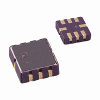
IC ACCELER DUAL AXIS DGTL 8-CLCC
Manufacturer
Analog Devices Inc
Datasheet
1.ADXL213EB.pdf
(12 pages)
Specifications of ADXL213AE
Acceleration Range
±1.2g
Axis
X, Y
Sensitivity
30°/g
Voltage - Supply
3 V ~ 6 V
Output Type
Digital
Bandwidth
1Hz ~ 500Hz Selectable
Mounting Type
Surface Mount
Package / Case
8-CLCC
No. Of Axes
2
Sensor Case Style
LCC
No. Of Pins
8
Supply Voltage Range
3V To 6V
Operating Temperature Range
-40°C To +85°C
Msl
MSL 1 - Unlimited
Lead Free Status / RoHS Status
Lead free / RoHS Compliant
For Use With
ADXL213EB - BOARD EVALUATION FOR ADXL213
Interface
-
Lead Free Status / RoHS Status
Lead free / RoHS Compliant, Lead free / RoHS Compliant
Available stocks
Company
Part Number
Manufacturer
Quantity
Price

Company:
Part Number:
ADXL213AE
Manufacturer:
ABOV
Quantity:
473
Part Number:
ADXL213AE
Manufacturer:
ADI/亚德诺
Quantity:
20 000
Company:
Part Number:
ADXL213AE-REEL
Manufacturer:
ALTERA
Quantity:
101


SPECIFICATIONS
T
are guaranteed. Typical specifications are not guaranteed.
Table 1.
Parameter
SENSOR INPUT
SENSITIVITY (Ratiometric)
ZERO g BIAS LEVEL (Ratiometric)
NOISE PERFORMANCE
FREQUENCY RESPONSE
SELF TEST
PWM Output
POWER SUPPLY
1
2
3
4
5
6
7
Guaranteed by measurement of initial offset and sensitivity.
Sensitivity varies with V
Defined as the output change from ambient-to-maximum temperature or ambient-to-minimum temperature.
Actual frequency response controlled by user-supplied external capacitor (C
Bandwidth = 1/(2 × π × 32 kΩ × C). For C
Self-test response changes with V
Larger values of C
A
Measurement Range
Nonlinearity
Package Alignment Error
Alignment Error
Cross Axis Sensitivity
Sensitivity at X
Sensitivity Change due to Temperature
0 g Voltage at X
Initial 0 g Output Deviation from Ideal
0 g Offset vs. Temperature
Noise Density
C
R
Sensor Resonant Frequency
Logic Input Low
Logic Input High
ST Input Resistance to Ground
Output Change at X
F
T2 Drift versus Temperature
Operating Voltage Range
Quiescent Supply Current
Turn-On Time
= –40°C to +85°C, V
SET
X
FILT
, C
Tolerance
Y
Range
6
5
X
7
, C
OUT
OUT
Y
increase turn-on time. Turn-on time is approximately 160 × C
, Y
S
, Y
. At V
OUT
OUT
OUT
1
4
S
, Y
= 5 V, C
2
S
= 3 V, sensitivity is typically 28%/g.
OUT
S
. At V
X
S
X
= 3 V, self-test output is typically 8%.
= C
, C
Y
= 0.002 μF, Bandwidth = 2500 Hz. For C
Y
= 0.1 μF, Acceleration = 0 g, unless otherwise noted. All minimum and maximum specifications
3
Conditions
Each axis
% of full scale
X sensor to Y sensor
Each axis
V
V
Each axis
V
V
@25°C
Self test 0 to 1
R
S
S
S
S
SET
Rev. A | Page 3 of 12
= 5 V
= 5 V
= 5 V
= 5 V, 25°C
= 125 kΩ
X
, C
Y
).
X
X
or C
, C
Y
= 4.7 μF, Bandwidth = 1 Hz. Minimum/maximum values are not tested.
Y
+ 4 ms, where C
X
, C
Min
27
0.002
22
4
30
3
Y
are in μF.
Typ
±1.2
±0.5
±1
±0.1
±2
30
±0.3
±50
±2
±0.25
160
32
5.5
50
23
1
±0.3
0.7
20
Max
33
4.7
42
1
6
1.1
Unit
g
%
Degrees
Degrees
%
%/g
%
%
%
mg/°C
μg/√Hz rms
μF
kΩ
kHz
V
V
kΩ
%
kHz
%
V
mA
ms
ADXL213
Related parts for ADXL213AE
Image
Part Number
Description
Manufacturer
Datasheet
Request
R

Part Number:
Description:
±1.7g Dual-Axis IMEMS Accelerometer Evaluation Board
Manufacturer:
Analog Devices Inc
Datasheet:

Part Number:
Description:
Inertial Sensor Evaluation System
Manufacturer:
Analog Devices Inc
Datasheet:
Part Number:
Description:
Manufacturer:
Analog Devices Inc
Datasheet:
Part Number:
Description:
Manufacturer:
Analog Devices Inc
Datasheet:
Part Number:
Description:
Manufacturer:
Analog Devices Inc
Datasheet:
Part Number:
Description:
Manufacturer:
Analog Devices Inc
Datasheet:
Part Number:
Description:
Manufacturer:
Analog Devices Inc
Datasheet:
Part Number:
Description:
Manufacturer:
Analog Devices Inc
Datasheet:
Part Number:
Description:
Manufacturer:
Analog Devices Inc
Datasheet:
Part Number:
Description:
Manufacturer:
Analog Devices Inc
Datasheet:
Part Number:
Description:
Manufacturer:
Analog Devices Inc
Datasheet:
Part Number:
Description:
Manufacturer:
Analog Devices Inc
Datasheet:
Part Number:
Description:
Manufacturer:
Analog Devices Inc
Datasheet: