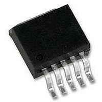
LM2595S-3.3 National Semiconductor, LM2595S-3.3 Datasheet - Page 11

LM2595S-3.3
Manufacturer Part Number
LM2595S-3.3
Description
IC, STEP-DOWN REGULATOR, TO-263-5
Manufacturer
National Semiconductor
Datasheet
1.LM2595T-5.0NOPB.pdf
(29 pages)
Specifications of LM2595S-3.3
Primary Input Voltage
12V
No. Of Outputs
1
Output Voltage
3.3V
Output Current
1A
No. Of Pins
5
Operating Temperature Range
-25°C To +125°C
Supply Voltage Range
4.5V To 40V
Lead Free Status / RoHS Status
Contains lead / RoHS non-compliant
Available stocks
Company
Part Number
Manufacturer
Quantity
Price
Company:
Part Number:
LM2595S-3.3
Manufacturer:
NS
Quantity:
17 445
Company:
Part Number:
LM2595S-3.3
Manufacturer:
NS
Quantity:
13
Part Number:
LM2595S-3.3/NOPB
Manufacturer:
NS/国半
Quantity:
20 000
Company:
Part Number:
LM2595S-3.3P+
Manufacturer:
NS
Quantity:
5 510
LM2595 Series Buck Regulator Design Procedure (Fixed Output)
LM2595 Series Buck Regulator Design Procedure (Adjustable Output)
Given:
V
V
I
F = Switching Frequency (Fixed at a nominal 150 kHz).
1. Programming Output Voltage (Selecting R
shown in Figure 1 )
Use the following formula to select the appropriate resistor
values.
Select a value for R
resistor values minimize noise pickup in the sensitive feed-
back pin. (For the lowest temperature coefficient and the best
stability with time, use 1% metal film resistors.)
Procedure continued on next page.
LOAD
OUT
IN
Voltage
Output
PROCEDURE (Adjustable Output Voltage Version)
(max) = Maximum Input Voltage
(V)
3.3
12
(max) = Maximum Load Current
5
= Regulated Output Voltage
Conditions
Current
Load
(A)
0.5
0.5
0.5
1
1
1
1
between 240
FIGURE 2. LM2595 Fixed Voltage Quick Design Component Selection Table
Max Input
Voltage
(V)
10
40
10
40
10
15
40
20
40
15
18
30
40
15
20
40
5
7
6
8
9
and 1.5 k . The lower
Inductance
(µH)
100
100
150
150
150
220
150
330
22
33
47
68
47
68
33
47
68
68
47
68
68
Inductor
1
and R
Inductor
2
L24
L23
L31
L30
L13
L21
L20
L28
L31
L30
L29
L21
L19
L19
L31
L30
L36
L35
L21
L19
L26
, as
( # )
11
Through Hole Electrolytic
HFQ Series
Panasonic
Given:
V
V
I
F = Switching Frequency (Fixed at a nominal 150 kHz).
1. Programming Output Voltage (Selecting R
shown in Figure 1 )
Select R
R
R
Example continued on next page.
LOAD
OUT
IN
330/16
270/25
220/25
180/35
220/25
150/35
150/35
330/16
220/25
180/35
180/35
180/16
120/25
100/25
220/25
180/35
180/25
2
2
(µF/V)
82/25
82/25
82/25
56/25
(max) = 28V
= 1k (16.26 − 1) = 15.26k, closest 1% value is 15.4 k .
= 15.4 k .
EXAMPLE (Adjustable Output Voltage Version)
(max) = 1A
= 20V
1
to be 1 k , 1%. Solve for R
PL Series
Nichicon
1200/25
330/16
270/25
220/35
220/35
220/16
150/25
330/16
220/25
180/35
120/35
180/16
100/25
220/25
120/25
180/25
(µF/V)
82/35
82/25
82/25
82/25
56/25
Output Capacitor
Surface Mount Tantalum
AVX TPS
220/10
220/10
220/10
220/10
220/10
100/16
100/16
220/10
220/10
220/10
100/16
220/10
100/16
Series
(µF/V)
68/20
68/20
68/20
68/20
68/20
68/20
68/20
68/20
2
.
(Continued)
595D Series
Sprague
1
330/10
270/10
220/10
180/10
220/10
150/16
100/20
270/10
220/10
150/16
120/16
150/16
100/20
120/20
120/20
100/20
120/20
100/20
www.national.com
(µF/V)
68/25
68/25
68/25
and R
2
, as


