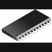
ACS709LLFTR-20BB-T Allegro Microsystems Inc, ACS709LLFTR-20BB-T Datasheet - Page 5

ACS709LLFTR-20BB-T
Manufacturer Part Number
ACS709LLFTR-20BB-T
Description
IC, CURRENT SENSOR, 11mA, QSOP-24
Manufacturer
Allegro Microsystems Inc
Series
-r
Specifications of ACS709LLFTR-20BB-T
Quiescent Current
11mA
Bandwidth
120kHz
Sensor Case Style
QSOP
No. Of Pins
24
Supply Voltage Range
3V To 5.5V
Operating Temperature Range
-40°C To +150°C
Polarization
Unipolar
Operating Supply Voltage (min)
3V
Operating Supply Voltage (typ)
3.3/5V
Operating Supply Voltage (max)
5.5V
Mounting
Surface Mount
Operating Temp Range
-40C to 150C
Operating Temperature Classification
Automotive
Current - Sensing
±37.5A
Accuracy
±2.5%
Sensitivity
56mV/A
Current - Supply
11mA
Sensor Type
Hall Effect
Voltage - Supply
3 V ~ 5.5 V
Output
2.5V
Frequency
120kHz
Response Time
4µs
Operating Temperature
-40°C ~ 150°C
Package / Case
24-SSOP (0.154", 3.90mm Width)
Lead Free Status / RoHS Status
Lead free / RoHS Compliant
Available stocks
Company
Part Number
Manufacturer
Quantity
Price
Company:
Part Number:
ACS709LLFTR-20BB-T
Manufacturer:
SAMTEC INC
Quantity:
13
Part Number:
ACS709LLFTR-20BB-T
Manufacturer:
ALLEGRO/雅丽高
Quantity:
20 000
ACS709
COMMON OPERATING CHARACTERISTICS
Characteristic
OVERCURRENT CHARACTERISTICS (continued)
Fault Enable (FAULT_EN Pin) Delay
Overcurrent Fault Response Time
Overcurrent Fault Reset Delay
Overcurrent Fault Reset Hold Time
Overcurrent Input Pin Resistance
VOLTAGE REFERENCE CHARACTERISTICS
Voltage Reference Output
Voltage Reference Output Load Current
Voltage Reference Output Drift
1
may be slightly degraded for V
2
3
4
5
6
7
8
fault switchpoint.
9
time FAULT_EN is raised from low to high, before the device is ready for responding to any overcurrent event.
Devices are trimmed for maximum accuracy at V
R
This parameter can drift by as much as 0.25% over the lifetime of this product.
This parameter can drift by as much as 0.3% over the lifetime of this product.
Calculated using the formula f
See page 8 on how to set overcurrent fault switchpoint.
Switchpoint can be lower at the expense of switchpoint accuracy.
This error specification does not include the effect of noise. See the I
Fault Enable Delay is designed to avoid false tripping of an Overcurrent (OC) fault at power-up. A 15 μs (typical) delay will always be needed, every
F(INT)
forms an RC circuit via the FILTER pin.
CC
3dB
values other than 5 V. Contact the Allegro factory for applications that require maximum accuracy for V
= 0.35 / t
9
r
.
High Bandwidth, Fast Fault Response Current Sensor IC
CC
Symbol
∆V
= 5 V. The ratiometry feature of the device allows operation over the full V
V
t
t
t
R
I
t
OCR
OCH
FED
ZCR
OC
ZCR
OC
ZCR
(continued) Valid at T
Set FAULT_EN to low, V
C
corresponding overcurrent threshold; then
reset FAULT_EN from low to high and
measure the delay from the rising edge of
FAULT_EN to the falling edge of ¯ F ¯ ¯ A ¯ U ¯ ¯ L ¯ ¯ T ¯
FAULT_EN set to high for a minimum
of 20 μs before the overcurrent event;
switchpoint set at V
delay from I
fault threshold to V
external C
Time from V
V
Time from V
fault latch; see Functional Block Diagram
T
T
Source current
Sink current
A
A
FAULT
OC
= 25°C, VOC pin to GND
= 25 °C
= 0 F; then run a DC I
NCOMP
> 0.8 × V
OC
P
FAULTEN
FAULTEN
Test Conditions
exceeding overcurrent
capacitor
specification in order to factor in the additional influence of noise on the
CC
A
¯ F ¯ ¯ A ¯ U ¯ ¯ L ¯ ¯ T ¯
OC
, R
= –40°C to 150°C, V
< V
pin < V
PU
= 0.25 × V
IL
OC
< 0.4 V, without
= 330 kΩ
to
P
IL
= 0.25 × V
In Thermally Enhanced Package
exceeding the
to reset of
CC
;
CC
CC
,
= 5 V, unless otherwise specified
115 Northeast Cutoff
1.508.853.5000; www.allegromicro.com
Allegro MicroSystems, Inc.
Worcester, Massachusetts 01615-0036 U.S.A.
Min.
50
–
–
–
–
2
–
3
–
0.5 × V
CC
Typ.
500
250
±10
1.9
15
range; however, accuracy
–
–
–
CC
CC
= 3.3 V.
Max.
–
–
–
–
–
–
–
–
–
Units
MΩ
mA
mV
μA
μs
μs
ns
ns
V
5


