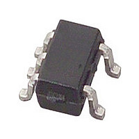
LM20BIM7X National Semiconductor, LM20BIM7X Datasheet - Page 5

LM20BIM7X
Manufacturer Part Number
LM20BIM7X
Description
IC,TEMPERATURE SENSOR,CMOS,TSSOP,5PIN,PLASTIC
Manufacturer
National Semiconductor
Datasheet
1.LM20BIM7X.pdf
(10 pages)
Specifications of LM20BIM7X
Rohs Compliant
NO
Temperature Sensor Function
Temp Sensor
Output Type
Analog
Package Type
SC-70
Operating Temperature (min)
-55
Operating Temperature (max)
130C
Operating Temperature Classification
Military
Operating Supply Voltage (min)
2.4V
Operating Supply Voltage (typ)
3.3/5V
Operating Supply Voltage (max)
5.5V
Lead Free Status / Rohs Status
Not Compliant
Available stocks
Company
Part Number
Manufacturer
Quantity
Price
Company:
Part Number:
LM20BIM7X
Manufacturer:
NSC
Quantity:
20 000
Company:
Part Number:
LM20BIM7X
Manufacturer:
NS
Quantity:
8 100
Part Number:
LM20BIM7X
Manufacturer:
NS/国半
Quantity:
20 000
Company:
Part Number:
LM20BIM7X/LM20/LM20BI/LM20B
Manufacturer:
YICHENG
Quantity:
100
Company:
Part Number:
LM20BIM7X/NOPB
Manufacturer:
National
Quantity:
22 265
Part Number:
LM20BIM7X/NOPB
Manufacturer:
TI/德州仪器
Quantity:
20 000
PCB Layouts Used for Thermal Measurements
1.0 LM20 Transfer Function
The LM20's transfer function can be described in different
ways with varying levels of precision. A simple linear transfer
function, with good accuracy near 25°C, is
Over the full operating temperature range of −55°C to +130°
C, best accuracy can be obtained by using the parabolic
transfer function.
solving for T:
A linear transfer function can be used over a limited temper-
ature range by calculating a slope and offset that give best
results over that range. A linear transfer function can be cal-
culated from the parabolic transfer function of the LM20. The
slope of the linear transfer function can be calculated using
the following equation:
T
min
Temperature Range
−55
−40
−30
−10
+35
+20
-40
V
(°C)
a) Layout used for no heat sink measurements.
O
= (−3.88×10
V
O
= −11.69 mV/°C × T + 1.8663 V
T
max
+130
+110
+100
+85
+65
+45
+30
−6
(°C)
×T
FIGURE 2. First order equations optimized for different temperature ranges.
2
) + (−1.15×10
FIGURE 1. PCB Lyouts used for thermal measurements.
10090829
−11.79 mV/°C × T + 1.8528 V
−11.77 mV/°C × T + 1.8577 V
−11.77 mV/°C × T + 1.8605 V
−11.67 mV/°C × T + 1.8583 V
−11.71 mV/°C × T + 1.8641 V
−11.81 mV/°C × T + 1.8701 V
−11.69 mV/°C × T + 1.8663 V
−2
×T) + 1.8639
Linear Equation
V
O
=
5
b) Layout used for measurements with small heat hink.
where T is the middle of the temperature range of interest and
m is in V/°C. For example for the temperature range of T
= −30 to T
and
The offset of the linear transfer function can be calculated us-
ing the following equation:
where:
•
•
Using this procedure the best fit linear transfer function for
many popular temperature ranges was calculated in
2. As shown in
linear transfer function increases with wider temperature
ranges.
V
the parabolic transfer function for V
V
parabolic transfer function for V
OP
OP
(T
(T) is the calculated output voltage at T using the
b = (V
MAX
MAX
) is the calculated output voltage at T
Maximum Deviation of Linear Equation from
= +100°C:
OP
m = −7.76 × 10
Figure 2
(T
MAX
m = −11.77 mV/°C
) + V
Parabolic Equation (°C)
T = 35°C
the error that is introduced by the
OP
(T) − m × (T
−6
× T − 0.0115,
10090830
±0.004
±0.004
O
±1.41
±0.93
±0.70
±0.65
±0.23
.
O
MAX
+T))/2
www.national.com
MAX
using
Figure
MIN


