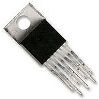
LM2679T-3.3 National Semiconductor, LM2679T-3.3 Datasheet - Page 12

LM2679T-3.3
Manufacturer Part Number
LM2679T-3.3
Description
Power Supply IC
Manufacturer
National Semiconductor
Specifications of LM2679T-3.3
No. Of Outputs
1
No. Of Pins
7
Output Current
5A
Peak Reflow Compatible (260 C)
No
Output Voltage
3.3VDC
Termination Type
Through Hole
Leaded Process Compatible
No
Mounting Type
Through Hole
Lead Free Status / RoHS Status
Contains lead / RoHS non-compliant
www.national.com
Application Hints
Using the nomographs and tables in this data sheet (or use
the available design software at http://www.national.com) a
complete step-down regulator can be designed in a few
simple steps.
Step 1: Define the power supply operating conditions:
Required output voltage
Maximum DC input voltage
Maximum output load current
Step 2: Set the output voltage by selecting a fixed output
LM2679 (3.3V, 5V or 12V applications) or determine the re-
quired feedback resistors for use with the adjustable
LM2679−ADJ
Step 3: Determine the inductor required by using one of the
four nomographs, Figure 3 through Figure 6 . Table 1 pro-
vides a specific manufacturer and part number for the induc-
tor.
Step 4: Using Table 3 (fixed output voltage) or Table 6 (ad-
justable output voltage), determine the output capacitance
required for stable operation. Table 2 provides the specific
capacitor type from the manufacturer of choice.
Step 5: Determine an input capacitor from Table 4 for fixed
output voltage applications. Use Table 2 to find the specific
capacitor type. For adjustable output circuits select a capaci-
tor from Table 2 with a sufficient working voltage (WV) rating
greater than Vin max, and an rms current rating greater than
one-half the maximum load current (2 or more capacitors in
parallel may be required).
Step 6: Select a diode from Table 5. The current rating of the
diode must be greater than I load max and the Reverse Volt-
age rating must be greater than Vin max.
Step 7: Include a 0.01µF/50V capacitor for Cboost in the de-
sign and then determine the value of a softstart capacitor if
desired.
Step 8: Define a value for R
rent limit to be at least 20% greater than Iout max to allow for
at least 30% inductor ripple current (
signs that must operate over the full temperature range the
switch current limit should be set to at least 50% greater than
Iout max (1.5 x I
FIXED OUTPUT VOLTAGE DESIGN EXAMPLE
A system logic power supply bus of 3.3V is to be generated
from a wall adapter which provides an unregulated DC volt-
age of 13V to 16V. The maximum load current is 4A. A soft-
start delay time of 50mS is desired. Through-hole compo-
nents are preferred.
Step 1: Operating conditions are:
Vout = 3.3V
Vin max = 16V
Iload max = 4A
Step 2: Select an LM2679T-3.3. The output voltage will have
a tolerance of
temperature range.
Step 3: Use the nomograph for the 3.3V device , Figure 3 .
The intersection of the 16V horizontal line (V
4A vertical line (I
tor, is required.
From Table 1, L46 in a through-hole component is available
from Renco with part number RL-1283-15-43.
±
2% at room temperature and
out
load
max).
max) indicates that L46, a 15µH induc-
ADJ
(Continued)
±
to set the peak switch cur-
3% over the full operating
±
15% of Iout). For de-
in
max) and the
12
Step 4: Use Table 3 to determine an output capacitor. With a
3.3V output and a 15µH inductor there are four through-hole
output capacitor solutions with the number of same type ca-
pacitors to be paralleled and an identifying capacitor code
given. Table 2 provides the actual capacitor characteristics.
Any of the following choices will work in the circuit:
2 x 220µF/10V Sanyo OS-CON (code C5)
2 x 820µF/16V Sanyo MV-GX (code C5)
1 x 3900µF/10V Nichicon PL (code C7)
2 x 560µF/35V Panasonic HFQ (code C5)
Step 5: Use Table 4 to select an input capacitor. With 3.3V
output and 15µH there are three through-hole solutions.
These capacitors provide a sufficient voltage rating and an
rms current rating greater than 2A (1/2 I
ing Table 2 for specific component characteristics the follow-
ing choices are suitable:
2 x 680µF/63V Sanyo MV-GX (code C13)
1 x 1200µF/63V Nichicon PL (code C25)
1 x 1500µF/63V Panasonic HFQ (code C16)
Step 6: From Table 5 a 5A or more Schottky diode must be
selected. For through-hole components only 40V rated di-
odes are indicated and 4 part types are suitable:
1N5825
MBR745
80SQ045
6TQ045
Step 7: A 0.01µF capacitor will be used for Cboost. For the
50mS softstart delay the following parameters are to be
used:
I
t
V
V
V
V
Using Vin max ensures that the softstart delay time will be at
least the desired 50mS.
Using the formula for Css a value of 0.148µF is determined
to be required. Use of a standard value 0.22µF capacitor will
produce more than sufficient softstart delay.
Step 8: Determine a value for R
current limit of at least 4A plus 50% or 6A.
Use a value of 6.2K .
ADJUSTABLE OUTPUT DESIGN EXAMPLE
In this example it is desired to convert the voltage from a two
battery automotive power supply (voltage range of 20V to
28V, typical in large truck applications) to the 14.8VDC alter-
nator supply typically used to power electronic equipment
from single battery 12V vehicle systems. The load current re-
quired is 3.5A maximum. It is also desired to implement the
power supply with all surface mount components. Softstart is
not required.
Step 1: Operating conditions are:
Vout = 14.8V
Vin max = 28V
Iload max = 3.5A
SST
SS
SST
OUT
SCHOTTKY
IN
: 50mS
: 16V
: 3.7µA
: 0.63V
: 3.3V
: 0.5V
ADJ
to provide a peak switch
load
max). Again us-


