DILER31120 MOELLER, DILER31120 Datasheet - Page 10
DILER31120
Manufacturer Part Number
DILER31120
Description
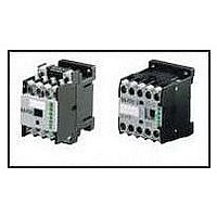
CONTACTOR
Manufacturer
MOELLER
Datasheet
1.DILER31120.pdf
(32 pages)
Specifications of DILER31120
No. Of Poles
3
Contact Configuration
3NO / 1NC
Relay Mounting
DIN Rail
Coil Voltage Vac Nom
120V
Relay Terminals
Screw Clamp
Nom Operating Power
25VA
External Width
45mm
External Depth
52mm
Contact Current Max
10A
Operating Voltage
415V
Load Current Inductive
6A
Load Current Resistive
10A
Rohs Compliant
Yes
Coil Type
AC
Lead Free Status / RoHS Status
Lead free / RoHS Compliant


10
DILMP Four-Pole Contactors
1
2
New 4-pole contactors from the xStart series
The new 4-pole contactor from Moeller optimized for AC-1 switched loads.
They are the specialists for applications where the mains is switched off or over,
heating systems are switched and 4-pole loads are switched.
Four compact contactors cover the performance range up to 200 A. The identi-
cal size for AC and DC operated contactors as well as a common range of acces-
sories for 3 and 4-pole contactors guarantee efficient and simple planning and
engineering.
4-pole contactor
AC-1
Conventional free air
thermal current Open
For DILMP20 to DILMP80 230 V 50 HZ 240 V 60 HZ, for DILMP125, DILMP160 and DILMP200 RAC240
For DILMP20 24 VDC, for DILMP32 to DILMP200 RDC24
20
32
45
63
80
125
160
200
l
A
th
=l
e
–
1N/O
1N/O
–
–
–
–
–
N/O
N/C
AC 230 V 50 HZ 240 V 60 Hz, o.RAC240
DC 24 V DC or RDC24
Part No.
Add voltage from above
DILMP20 (…)
DILMP32-10 (…)
DILMP45-10 (…)
DILMP63 (…)
DILMP80 (…)
DILMP125 (…)
DILMP160 (…)
DILMP200 (…)
110 V 50 HZ 120 V 60 Hz, 24 V 50/60 Hz,
2
1
,
Combination plug connections
These combinations always consist of
universal standard components which
offer a constantly high level of quality
at an attractive price due to the large
production volumes involved. With
contactors < 16 A DIL M12-XSL or
DIL M12-XRL star-delta and reversing
starter wiring kits can be fitted in the
plug connectors rapidly and with
optimum space saving.
Wiring
The coil terminals are now arranged at
the front of the contactors. As they are
no longer covered by main current wiring
that is often rigid, this simplifies and
reduces the time required for wiring
work and voltage testing. The terminals
of the integrated auxiliary contact are
arranged on the second level.
Related parts for DILER31120
Image
Part Number
Description
Manufacturer
Datasheet
Request
R

Part Number:
Description:
3NO&1NC MINIATURE RELAY-AC OPERATED
Manufacturer:
MOELLER
Part Number:
Description:
SWITCH HEAD E/P / R-ATO HEAD (0043065) MOELLER
Manufacturer:
MOELLER

Part Number:
Description:
BASIC UNIT, PLASTIC, 1N0/1NC, IP66
Manufacturer:
MOELLER
Datasheet:


Part Number:
Description:
Industrial Control Relay
Manufacturer:
MOELLER
Datasheet:
Part Number:
Description:
CONTACTOR, 4PST-NO, 120VAC, DIN RAIL
Manufacturer:
MOELLER
Datasheet:
Part Number:
Description:
CONTACTOR, 4PST-NO, 24VDC, DIN RAIL
Manufacturer:
MOELLER
Datasheet:


Part Number:
Description:
FRONT FIXING, LED, 85-264VAC, BLUE
Manufacturer:
MOELLER
Datasheet:

Part Number:
Description:
REAR FIXING, LED, 18-30VAC/DC, GRN
Manufacturer:
MOELLER
Datasheet:
Part Number:
Description:
REAR FIXING, LED, 18-30VAC/DC, RED
Manufacturer:
MOELLER
Datasheet:
Part Number:
Description:
REAR FIXING, LED, 18-30VAC/DC, WHT
Manufacturer:
MOELLER
Datasheet: